14
\$\begingroup\$

I want to know what kind of periodic test we use to test if a current-limiting fuse will normaly open and protect an electronic circuit (a battery charger) if a failure occur (short circuit or over current). Assume that I have a fuse that supports 5A of current and that if current is above this value it will damage the battery cells (venting). If the fuse, which is the last resort in my protection scheme, does not open (stuck) then my circuit will be damaged.

What is the periodic test we can use to be sure that the fuse can safely open in case of short circuit or the current is above the max value (5A in this example)?

\$\endgroup\$
10
  • 3
    \$\begingroup\$ It's very difficult to test fuses properly because not only is the fusing current important, but the rate of change of the current through the fuse and the ambient temperature play a very large part in how long it takes the fuse to blow. That, of course, will determine how long your widget will be exposed to overcurrent and, in fact, whether it'll be protecting the fuse. What, specifically, do you want to test for? Just so you'll know what you're up against, here's a good read: \$\endgroup\$
    – EM Fields
    Commented Jan 8, 2015 at 10:37
  • \$\begingroup\$ You're not telling us several things that turn out to matter in the selection of fuses... (if you read a profi text on fuses, like Wright and Newbery Electric Fuses, 3rd ed.) What is the valuable/expensive stuff in your circuit that you want to protect? Semiconductors? Capacitors? Transformers? Motors? It turns out all these have slightly different selection criteria for their protection fuses. Additionally, what voltages are we talking about? AC or DC? Even that matters! \$\endgroup\$ Commented Jan 8, 2015 at 11:13
  • 7
    \$\begingroup\$ "pity the poor fuse ... when it does its job, we say it has failed" (anon BBC engineer) \$\endgroup\$
    – user16324
    Commented Jan 8, 2015 at 12:33
  • 1
    \$\begingroup\$ In industrial applications the fuse is initially selected (Maximum permissible size) based on the size of wiring to the device (Wiring codes) and any requirements of the device (which may be the result of testing under fault conditions). Indeed some testing I have done required "a nonrenewable fuse that conducts twice its rated current for at least 12 seconds" . From this and other conversations I was educated to treat fuses as protection for wiring and connectors only unless you go for something like a semiconductor fuse. \$\endgroup\$
    – Spoon
    Commented Jan 8, 2015 at 13:14
  • 1
    \$\begingroup\$ For protection of semiconductors against faults, the \$I^2t\$ rating of the fuse is very important. See, for example, this guide from Schurter. \$\endgroup\$ Commented Jan 8, 2015 at 15:39

6 Answers 6

21
\$\begingroup\$

I think maybe you misunderstand how a fuse behaves.

A fuse doesn't instantly open when current meets the Ampere Rating. There is a minimum Opening Time at 100% of Ampere Rating, and there will also be maximum Opening Time at higher currents such as 200% or 1000% of Ampere Rating.

For example, a Littelfuse 0251005.NRT1L (data sheet http://www.littelfuse.com/~/media/electronics/datasheets/fuses/littelfuse_fuse_251_253_datasheet.pdf.pdf ) lists the following:

  • 100% of Ampere Rating: Opening Time 4 Hours Min
  • 275% of Ampere Rating: Opening Time 300 ms Max
  • 400% of Ampere Rating: Opening Time 30 ms Max
  • 1000% of Ampere Rating: Opening Time 4 ms Max

So this 5A fuse with 5A of current flowing through it, is guaranteed NOT to open for at least 4 hours. But when the current exceeds 13.75A, this fuse is guaranteed to open within 300 ms. If the current reaches 50A then the fuse opens very quickly. But if the current is only 10A, the fuse won't open instantly.

If you use a 2A Ampere Rating fuse instead, then the 275% of Ampere Rating poing is 5.5A, which is closer to what you want in your example. But if your application typically draws more than 2 amps, then the 2A rated fuse will blow sometimes. Especially if the equipment is left on for a long period of time.

Fuses just don't have a very tightly controlled "open fail" current. They are one-time-use devices; once a fuse is tested to the point of opening, that fuse is permanently destroyed -- so statistical process control is the only practical way to ensure that the fuses are likely to work.

You could perform the same kind of testing. If you're building a batch of 500 devices, purchase a reel of 5000 fuses. (Again I'm assuming picofuse, which look similar to axial leaded 1/4 watt resistors. Glass tube fuses don't come in tape and reel.) When you get that big batch of fuses, you randomly pull out some samples, maybe 100 fuses. Test at two different conditions: - must sustain current below 100% Ampere Rating for xx time - must always open within xx time at test current 275% Ampere Rating (this is the destructive part of the test)

The more fuses you test, the more closely the tested sample will resemble the untested fuses, and the more confident you will be that the fuses work as advertised. But the more time and money you will be spending, to fill the trash can with used fuses.

Further downside is that if you conclude from your testing that this particular reel of fuses is not up to your standards, the distributor might not accept returns of a partial reel. So you'd be out $1400.

\$\endgroup\$
12
\$\begingroup\$

A fuse cannot be relied upon to protect any circuit from over-current. If your circuit draws an excessive current (from a voltage supply it is expected to handle) then it is faulty already.

A fuse prevents fire (normally) by protecting feed cables from taking to much current for too long a period and melting. The impact of cables melting is much more serious of course and can lead to electrocution and even bigger fires. Fuses do not protect a piece of electronics from failure.

If you want over-voltage protection then this is a different story and a fuse in conjunction with a zener diode (or crowbar circuit) can do this.

You have to remember that a fuse rated at 5 amps will carry that current indefinitely.

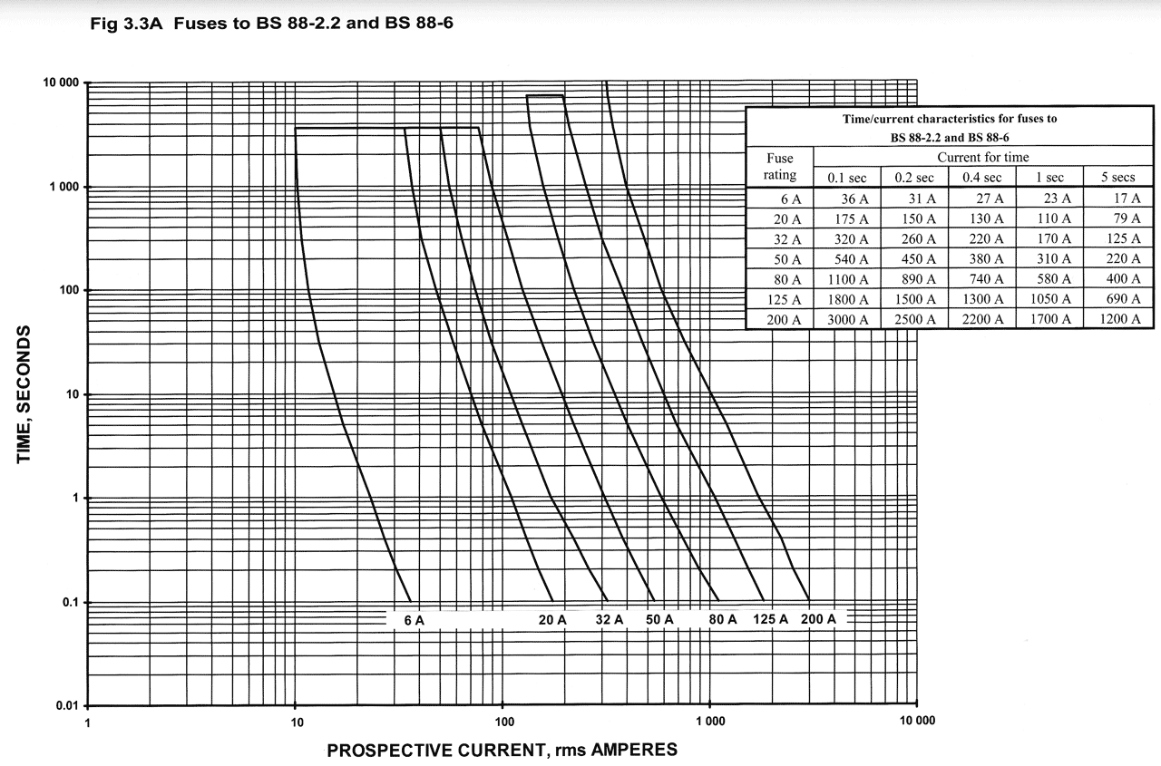
enter image description here

If you look at the curves above the 6A fuse might "break" at 36 amps in 0.1 seconds or take 5 seconds to "break" at 17 amps. This means a fuse does not current limit - it thermally protects.

\$\endgroup\$
7
  • \$\begingroup\$ "Fuses do not protect a piece of electronics from failure." isn't necessarily true, considering that a fuse between the output of an audio amplifier and a speaker could well keep their magic smoke from escaping while sacrificing its own. \$\endgroup\$
    – EM Fields
    Commented Jan 8, 2015 at 11:25
  • \$\begingroup\$ @EMFields - the fuse wouldn't protect against instantaneous current overload failure of transistors but it would likely protect against average power overload. In your example, the fuse is "protecting" up-stream (rather than down-stream) components - the op is talking about the fuse being the "last resort" and I take that to mean that it is in the power feed to the circuit he wishes to protect. I reckon the fuse, in your example would protect the speaker should a transistor short out though. Maybe the op could clarify? \$\endgroup\$
    – Andy aka
    Commented Jan 8, 2015 at 11:45
  • \$\begingroup\$ "A fuse cannot be relied upon to protect any circuit from over-current." This is alas blatantly false if you read a professional text like Wright and Newbery, Electric Fuses, 3rd ed. Fuses provide plenty of over-current protection when selected properly... which however is as (you correctly say) not done by using an X amp fuse. It's mostly a matter of the Joule integral (I^2t) of the fuse being below what the device can handle. It gets complicated from there, depending on the device. \$\endgroup\$ Commented Jan 8, 2015 at 11:47
  • \$\begingroup\$ @RespawnedFluff I am talking about instantaneous over-current. In what way (specifically) is what I've said blatantly false? You then appear to be agreeing with me that it's joule-seconds that a fuse protects against. What precisely are you saying? Maybe there is a link to the document you mention? \$\endgroup\$
    – Andy aka
    Commented Jan 8, 2015 at 11:54
  • \$\begingroup\$ Instantaneous over-current (for an absurdly small amount of time) will not destroy a device, only the Joule integral will. Precisely the same thing that destroys the fuse. How do you propose a fuse prevents fires if doesn't limit current in a meaningful way through anything? Also, a circuit may not be 100% faulty. Some component may have failed or even user error may have occurred. Limiting the energy that gets dumped into the circuit in such a case may save some of its other components. Or at least that's what the fuse book tells me. \$\endgroup\$ Commented Jan 8, 2015 at 12:01
5
\$\begingroup\$

This isn't a direct reply to the question, but then again, most of the other replies here aren't either, they just state some more or less correct facts about fuses in general, and the protection they may or may not provide to equipment. Here's the general advice from Wright and Newbery's Electric Fuses, 3rd ed., p. 139, before it gets to specifics, specifics which depend on the device protected.

First, the minimum fusing current of the fuse should be slightly below the current which the cables and item of equipment are able to carry continuously.

The item of equipment will usually be able to carry overload currents for limited periods, and the fuse should operate at these current levels in times slightly shorter than the corresponding equipment time ratings. [This refers to the Joule integral as it turns out later.]

Higher currents may flow as a result of faults within the item of equipment and in these circumstances the primary requirement is that consequential damage to the remainder of the circuit should be prevented.

Once we learn more details from the OP beyond the 5A requirement, which is basically just meeting the requirement of the first paragraph in the quote, we'd be able to say more.

If you need more from the book:

IEC TR 61818, an application guide for low-voltage fuses, gives a summary of the advantages of current limiting fuses and it is felt appropriate to draw readers attention to these benefits. Many of these benefits also apply to high-voltage and miniature fuses [...] • Cost-effective protection: compact size offers low-cost over-current protection at high short-circuit levels. • No damage for type 2 protection according to IEC 60947-4-1 and IEC 60947-4-2. By limiting short-circuit energy and peak currents to extremely low levels, fuses are particularly suitable for type 2 protection without damage to components in motor circuits.

So it seems fuses do offer over-current protection at least in the sense that fuse experts use this term...

\$\endgroup\$
1
  • 1
    \$\begingroup\$ Ok, whoever downvoted this, it would surely help to explain what is that you disagree with. \$\endgroup\$ Commented Jan 8, 2015 at 12:57
4
\$\begingroup\$

I am going to assume that you mean a fuse and not a circuit breaker. This means that once the fuse has blown, you will have to replace it.

A fuse consists of a conductor made out of a special material that will melt when a certain amount of current flows through it. This being said, fuses are extremely reliable. They are enclosed to prevent any unwanted reactions with the environment.

Just about the only thing that can go wrong with a fuse is a voltage arc. Fuses have a maximum voltage rating and if exceeded it can cause an arc across the fuse which will most likely cause damage to the electronics.

If you check the voltage rating, and you know you have the correct maximum current fuse, then I would not recommend you test it at all.

But, if you want to test it then you can remove the fuse and attach a power supply to it. This will create a short circuit and should blow the fuse.

\$\endgroup\$
3
  • \$\begingroup\$ The OP didn't ask for a test to destruction with no data taken. -1 \$\endgroup\$
    – EM Fields
    Commented Jan 8, 2015 at 9:44
  • 2
    \$\begingroup\$ I'm actually curious how you'd test a normal, fusible fuse without actually destroying it. One should, of course, in addition measure (or better record on a scope with memory etc.) the current transient while blows. The answer could certainly be improved, but unless there's a dramatically different method... like ensuring the tested fuse can be reused... I'm no convinced Addison deserves the downvote. \$\endgroup\$ Commented Jan 8, 2015 at 9:47
  • \$\begingroup\$ @RespawnedFluff: Then upvote Addison, flag my comment, and improve the answer. \$\endgroup\$
    – EM Fields
    Commented Jan 8, 2015 at 10:41
4
\$\begingroup\$

The test you can perform on a periodic basis that will prove that your circuit survives up to 5A could be done in the following way.

  1. Remove the actual fuse from the fuse holder in the product to be tested.

  2. Replace the fuse with a two wire connections that go to a special test fixture. This could be a connection device shaped like a fuse that has the two wires soldered to its ends and then plugs into the fuse holder.

  3. The special test fixture is a thing that you would build that can sense the current through the two wires. The two wires pass through a small valued current sense resistor and a pair of relay contacts that are normally closed. When the test fixture senses current at 5A it opens the relay and latches into that state until some button is pressed to ready the test fixture for the next test.

  4. Another part of the test fixture is designed in the proper way (specific to your product) that either injects current into or loads some part of your circuit in a linear manner from 0A up to a maximum of say MAX-A. For example, if your product circuit is designed as a voltage converter to supply a load of up to 5A at output voltage of 12V the test fixture could be designed as an active current sink load that is controlled to sink from 0 to MAX-A in a ramped manner.

  5. Power up the product under test.

  6. Activate the test fixture to start the ramp up of the current from 0 to MAX-A.

  7. Check that the test fixture sensed the current at 5A and latched the relay open.

  8. Turn off the power to the product under test and remove the connections from the test fixture and replace the fuse.

  9. Check that there are no burned components in the product under test.

  10. Perform the normal functional test on the product to assure that it still works correctly.

That should give you the idea of the test flow and the testing equipment that you need to build. It is clearly product specific to work out how the 0 to MAX-A current device gets designed and attached to the circuit.

You may decide to change the 5A test current level to a value that is 20% or 40% higher so that you provide some test margin to assure that the circuit in your product is fully robust all the way up to and over the 5A spec limit.

\$\endgroup\$
2
\$\begingroup\$

Fuses are not a great measure to protect circuits with hard current limits; they are there to protect the user from fire and electrocution risks.

A 5A IEC fuse will conduct continuously at 5A. And for quite a long time at 5.1A. And for some time (milliseconds to seconds) at 10A. The exact characteristics are in the datasheet; presumably they're determined by modelling the fuse wire and verified by destructive testing samples from production.

http://www.schurter.co.uk/content/download/194051/5552460/file/Guide_to_Fuse_Selection.pdf

\$\endgroup\$

Your Answer

By clicking “Post Your Answer”, you agree to our terms of service and acknowledge you have read our privacy policy.

Not the answer you're looking for? Browse other questions tagged or ask your own question.