1
\$\begingroup\$

I am installing a bunch of LM317 and LM337 regulators in TO-220 package. They will have 2 heat sinks on them each. Occasionally they will have to run close to their maximum continuous rating and can get hot. My question is about the heat transfer between the regulators and their heat sinks. Using nothing is easiest.

I would like to know how much better either the tape or paste is over using nothing.

3M has many Thermal transfer tapes. I am not sure which one would be good for this application.

enter image description here

\$\endgroup\$
2
  • 3
    \$\begingroup\$ I hope those devices aren't going into an environment with any vibration. The legs will fatigue and break in a hurry. Have you considered using proper, PCB-mounted heatsinks? \$\endgroup\$ Commented Jan 9, 2015 at 10:16
  • \$\begingroup\$ Consider re-rating it by using an LM338 instead of an LM317. Pin compatible, and doesn't even break a sweat at 1A... \$\endgroup\$
    – Majenko
    Commented Jan 9, 2015 at 10:35

2 Answers 2

4
\$\begingroup\$

I would like to know how much better either the tape or paste is over using nothing.
3M has many Thermal transfer tapes.
I am not sure which one would be good for this application.

Using "something" is good.
Choice is as much based on mess, ease and cost as effectiveness - as most systems that work at all work well enough in most cases.

Usually Rth_sa (thermal resistance heat sink to air) is the main factor.
Rjc (junction-case) is set by the manufacturer and is usually good enough if you do your part OK.
Rcs (case-sink) which you are asking about here is usually not the major factor as long as you do it half well. It's usually only in super high power applications that Rjc and Rcs matter crucially as then Rsa needs to be very low and the rest start to matter more.

As well as what you mention you can get thermally conductive rubber washers - these are what I usually use and they have the advantage of electrical isolation as/if desired.

The advantage of any jointing method designed for the purpose is that it provides intimate contact with heatsink and device and avoids air voids. Air is a poor heat conductor and quite small air voids across a surface can noticeably increase thermal resistance. Using no compound etc makes consistency harder to obtain.

Manufacturers provide data on performance but you can easily check by making several devices which are the same except for jointing material, running each at the same and highish wattage and measuring device to sink temperature drop. If you can comfortably touch the IC at full cry when temperature has stabilised it is usually OK enough - under 55 degrees C case if you can hold a thumb on it for many seconds. For first test dab with a wetted finger or other material - to avoid leaving skin on the device.

A mere whiff of forced air flow makes a vast difference to heatsink performance. In purely passive systems working on helping air flow can also help muchly. Avoid arrangements which block flow unnecessarily.


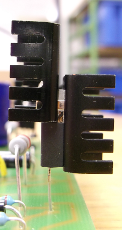
If you intend to mount the heatsinks as per photo, strongly consider not doing so. In an ideal vibration free environment they may last OK but in most real world conditions that is risking fracture of the leads with time.

Better would be a single heatsink on one side extending down to the PCB and screwed or otherwise anchored to the PCB in some way. Even attachment with eg neutral cure silicon rubber would be better than waving in the breeze. A single heatsink may also give some gains in heat transfer per area. Mount the TO220 device with short leads near the PCB so the majority of the heatsink is above it.


The long leads on the power resistor at rear helps prevent board charrin in extremis BUT makes resistor cooling worse. You can get a useful amount of cooling from PCB pads when the leads are short and copper area is maximised. For reliability resistors should be run at 1/2 max power or less so usually temperatures should not be so high as to damage PCBs.

If the regulator drops substantial voltage always consider using a series resistor to move heat out of the regulator. The resistor should be sized such that the regulator has enough voltage headroom at Vin_min and Iout_max. A 5W ceramic bodied micro-brick style resistor dissipating say 2 Watts is easily air cooled and takes 2 Watts off the cooling needed by the regulator. A 10 W resistor can happily dissipate up to say 5 W and if you need more than that your design is usually suspect with LM317 etc. LM350 at full cry is harder.
\$\endgroup\$
1
  • \$\begingroup\$ Mounting the 2 heatsinks and the paste was not my idea, and the regulator is top heavy. In the past they were installed with one heat sink, and no paste and they were fine. One of the regulators limits the current and the power resistor 2.4 Ohm sets current to 0.5A max. It doesn’t get too hot. I have mounted the resistor higher because of a future modification, another resistor can be soldered to it, increasing the current to 0.75A. The extra heat sinks and the paste is for that future change. \$\endgroup\$
    – sparky Al
    Commented Jan 9, 2015 at 17:32
2
\$\begingroup\$

whether or not a thermal interface material (TIM) is of use depends on varying factors.

The most important function of such materials is to fill roughness of opposing planes. These cavities contain air in thin layers. These air volumes have the one of the worst thermal conductivities one can think.

If you have two even and perfectly polished metal sheets pressed to each other, these air gaps can be neglected and inserting a TIM will increase the thermal resistance instead of lowering it. This is, because almost any TIM contains particles which coerce a minimum thickness of the intermediate layer.

But in reality there are usually no polished surfaces. The slug of your semiconductor will exhibit mold flash and the heatsinks will have some sort of striations from extrusion moulding.

In your case it depends from the thermal power to dissipate. If you calculate the maximum dissipation for a LM317, you get roughly 60 W. Assuming 35°C ambient temperature, you have a difference of 115°C which means a cumulated thermal resistance less than 2°C/W is needed. It is even impossible to keep the die within spec if you tie the heat slug perfectly to the environment, because the thermal resistance of the heat slug is already 3°C/W.

But I guess you haven't that case, because I don't assume you want to build an electric radiator. You will be better off if you calculate or estimate. the real loss of your regulator for several operating points.

Generally for TO-220 I recommend using a thin (100 µm) conductive foil or phase change material, because it is a good trade off between handling and conductivity.

\$\endgroup\$
1
  • \$\begingroup\$ The paste is messy, but adjusts best to the application. Tape is not messy, but since the heatsink is fastened by one bolt that is not in the middle, it could make the transfer surfaces smaller as the tension is not uniform, and the tape could flex a bit and cause tilting. Using nothing would rely on the contact under the bolt, which would be smaller but still decent \$\endgroup\$
    – sparky Al
    Commented Jan 9, 2015 at 17:05

Your Answer

By clicking “Post Your Answer”, you agree to our terms of service and acknowledge you have read our privacy policy.

Not the answer you're looking for? Browse other questions tagged or ask your own question.