0
\$\begingroup\$

I came across the following automotive wiring diagram:

Automotive wiring diagram

One thing I don't quite understand is the way they wired the relay. I've got two main questions.

  1. It appears to me that they used the exact same wire from terminal 87 to provide power to terminal 86. I don't think that there is anything wrong with this approach, but I haven't seen it before. The exact same wire gauge is used although one would expect that the load (the radiator fan) draws more current than the relay coil, right? Why did they do it this way?

  2. Why did they connect battery positive (30) to terminal 87 on the relay? Why didn't they use terminal 30 on the relay? It makes no sense to me, but I guess there must be a good reason.

\$\endgroup\$
3
  • \$\begingroup\$ I'm really not getting your point...if the coolant is hot, the relay switches the radiator fan on. Seems logical enough to me. \$\endgroup\$
    – markt
    Commented Jan 16, 2015 at 23:57
  • \$\begingroup\$ I'm a beginner, so please bear with me. I'm sure this works like it's supposed to, but I'm not used to seeing a relay wired like this. \$\endgroup\$ Commented Jan 17, 2015 at 0:00
  • \$\begingroup\$ "DIN standard - we don't need no stinkin DIN std" :-). ie often enough people will wire something like this is a manner which makes sense functionally without regard to there being "proper" numbering. That's life. \$\endgroup\$
    – Russell McMahon
    Commented Jan 17, 2015 at 10:14

3 Answers 3

5
\$\begingroup\$

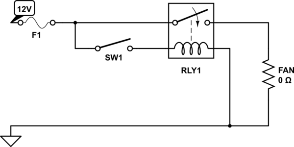
There is absolutely nothing strange there - it's just how they've drawn it that's strange. Let me re-draw it as a proper schematic for you:

schematic

simulate this circuit – Schematic created using CircuitLab

When the switch turns on the relay activates and power flows to the motor (depicted as a lamp here - circuitlab doesn't have a motor).

Why did they wire the battery to pin 87 and not pin 30? Simply because then the motor would be on all the time and the relay would do nothing.

Why did they use the same gauge wire? Simple economy of scale. They're already using that gauge elsewhere, so why fork out on a different, smaller, gauge as well when they don't need to?

\$\endgroup\$
12
  • 1
    \$\begingroup\$ Well, they did use 20-gauge wire from the relay's coil (pin 85) to ground. So it is a good question why the wire from the switch to the relay's other coil pin (#86) is 14-gauge. Assuming I'm reading the OP's diagram correctly... which I might not. \$\endgroup\$ Commented Jan 17, 2015 at 0:21
  • 1
    \$\begingroup\$ But not in brown and red, only in brown. Having brown and red in 20 gauge is a whole new reel of cable. \$\endgroup\$
    – Majenko
    Commented Jan 17, 2015 at 0:23
  • \$\begingroup\$ Why would the motor be on all the time if terminal 30 was used? \$\endgroup\$ Commented Jan 17, 2015 at 0:23
  • 1
    \$\begingroup\$ I would say the pin on the relay numbered 30 should actually be numbered 87b. Probably someone in the draft shop getting mixed up is all - since the wire eventually makes its way to 30 once it's gone through the relay. \$\endgroup\$
    – Majenko
    Commented Jan 17, 2015 at 0:34
  • 2
    \$\begingroup\$ One reason to use the AWG 10 wire all the way to terminal 86 is so that if there's a short in that part of the circuit you know the fuse F1 will blow before the shorted wire sets something on fire. At least that's how its done in residential wiring --- the size of the circuit breaker determines the guage of wire you need to use. \$\endgroup\$
    – The Photon
    Commented Jan 17, 2015 at 5:08
4
\$\begingroup\$

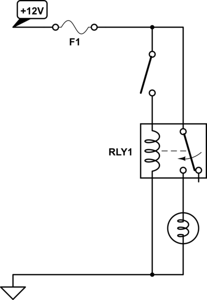
If you draw this as a schematic, it would look like:

schematic

simulate this circuit – Schematic created using CircuitLab

Terminals 30 and 87 are electrically equivalent - the circuit will work the same, regardless of which way they are connected.

The connection from terminal 87 to 86 goes through the thermal switch, so the switch will control the fan.

\$\endgroup\$
3
  • \$\begingroup\$ "Terminals 30 and 87 are electrically equivalent - the circuit will work the same, regardless of which way they are connected." — And that's exactly why I don't understand that they used 87 instead of 30. Why wouldn't they conform to the DIN standard? \$\endgroup\$ Commented Jan 17, 2015 at 0:29
  • 1
    \$\begingroup\$ Terminals 30 and 87 are not equivalent. They are the 2 ends of the relay contacts. They are only connected when the relay coil is energized. The relay coil is only energized when the coolant switch closes. If power were applied directly to pin 30, then the fan would always be on which is not what is wanted. \$\endgroup\$
    – Barry
    Commented Jan 17, 2015 at 1:25
  • 1
    \$\begingroup\$ @barry: 87 and 30 are equivalent, in the sense that if all connections on terminal 87 are moved to 30, and vice versa, the circuit would still work. \$\endgroup\$ Commented Jan 17, 2015 at 1:43
1
\$\begingroup\$
  1. Using bigger size wire for the relay coil, to reduce inventory, is okay.

  2. The relay terminal numbers shown do not comply to standards.

Correct terminal numbers are 85 - Relay coil +ve, 86 - Relay coil -ve, 87 - Relay contact common, 87b - Normally open contact.

Reference - DIN 72552 http://en.wikipedia.org/wiki/DIN_72552.

\$\endgroup\$
1
  • \$\begingroup\$ All the relays I've got have a terminal 30. I guess none of them comply to the standards. \$\endgroup\$ Commented Jan 17, 2015 at 19:03

Your Answer

By clicking “Post Your Answer”, you agree to our terms of service and acknowledge you have read our privacy policy.

Not the answer you're looking for? Browse other questions tagged or ask your own question.