3
\$\begingroup\$

I was looking for a strain gauge shield for an Arduino Mega. I found this link which I found really useful:

http://www.osengr.org/Projects/Load-Cell-Shield/Load-Cell-Shield.html

At the bottom of the web page linked above, the details regarding the circuitry have been made available for downloading.

But I have not built this shield yet as I have bumped into a few problems. I will need to measure the voltage output from around 24 strain gauges (putting them in a half-bridge configuration). So, I was thinking of having only one Wheatstone bridge on the shield and having all the gauges taking turns in interacting with the same bridge. Sorry if this sounds silly, but I was hoping to achieve this using a multiplexer (even though more I think about it, it seems more impossible), so I don't end up making 12 bridges.

Let's say that the previous approach is impossible and I have to make individual bridges per pair of strain gauges. Could I still use a 16-channel MUX like HEF4067B to allow each bridge take turns in signal amplification and analogue to digital conversion through the AD7730 chip? By doing this I want to prevent using an amplifier chip like AD7730 or INA126 for every single bridge. Also I wanted to use the multiplexer to overcome the limited number of analogue inputs on the Mega.

This way I can use only two analogue pins on the Mega for taking to potentially 32 sensors (16 channels on each analogue pin). Do you think my line of thinking is reasonable or am I really off?

Actually I think this is my main issue at the moment and what I mentioned above are my thought/solutions. I apologize if they are really far-fetched and I really appreciate any help on this matter.

\$\endgroup\$
1
  • 1
    \$\begingroup\$ Maybe. Do look at the effect of on resistances and look at any offset or bias currents and voltages the gates may introduce. Look at the specs for the el-cheapo gates you mention and some more expensive higher spec ones and see if the difference they make for you is worthwhile - or essential. \$\endgroup\$
    – Russell McMahon
    Commented Feb 16, 2015 at 10:50

2 Answers 2

3
\$\begingroup\$

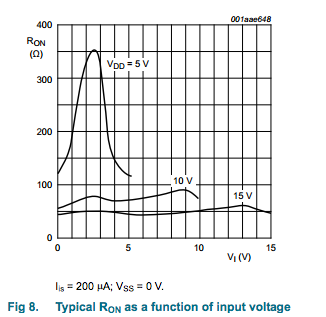
Your first approach is unlikely to work very well because analog multiplexers don't exhibit good resistance matching between channels - in the case of HEF4067B, it's listed as up to 25 ohms mismatch. They also exhibit variable on resistance over voltage:

enter image description here

Your second approach should work because current won't be flowing through the MUX, meaning the mismatched resistance won't have much effect on the output reading. It may still result in offset errors that you need to correct per-gauge, but you'll have to calibrate them independently.

Another option would be to look for an analog frontend suitable to your application. There exist precision DACs with differential input, programmable gain, and multiplexed frontends, such as ADS1243 from TI, which would allow you to implement your entire front-end - mux, amplify and convert - in a single IC.

\$\endgroup\$
3
  • \$\begingroup\$ Much appreciated.I really admire your capability to analyze the characteristics of the chip and understand the graph and its relation to my application. Would you please be able to let me know of some reference books, videos etc which can be helpful in understanding the idea with "resistance mismatching", "R on" with their relation to MUX. Also, when you mention in my second approach that no current won't be flowing through the MUX, how do you mean and how can that be? Moreover, I really love the third option that you mentioned and will surely look into it. \$\endgroup\$
    – Jamy codes
    Commented Feb 16, 2015 at 13:26
  • 1
    \$\begingroup\$ The issue is simply this: analog switches have significant resistance - for the one you listed it's on the order of 100-300 ohms - and the resistance can vary from channel to channel. Since your proposal requires (correct me if I'm wrong) inserting the analog mux in the middle of the bridge, that resistance adds to the effective resistance of the bridge resistors. If the two channels' resistance isn't exactly the same, they contribute unevenly, and unbalance the bridge. When current passes through them, it creates an offset voltage that could be very large. \$\endgroup\$ Commented Feb 16, 2015 at 13:55
  • 1
    \$\begingroup\$ In your second option, you're inserting the analog switch between the full bridge and the instrumentation amp, and the input of the instrumentation amp draws very little current indeed - in the case of the INA126 it's on the order of nanoamps - so it doesn't matter much if the resistances for the two channels aren't closely matched, because very little current means very little voltage develops across them. \$\endgroup\$ Commented Feb 16, 2015 at 13:57
2
\$\begingroup\$

I think this will be OK.

Have one pair of fixed resistors forming the "bridge completion potential divider" for all the half bridge circuits. This connects permanently to one of the inputs on your instrumentation amplifier. All the active half bridge circuits connect to individual ports on the 4067 with the common pin on the 4067 going to the other input pin on the InAmp.

Make sure that your excitation voltage can supply all the half-bridges and you should be in business.

\$\endgroup\$
0

Your Answer

By clicking “Post Your Answer”, you agree to our terms of service and acknowledge you have read our privacy policy.

Not the answer you're looking for? Browse other questions tagged or ask your own question.