1
\$\begingroup\$

I am planning to use an AD7730L analogue to digital converter (ADC) chip, with a quarter bridge circuit. Everything was on the track until I realised something, which indicated that things were perhaps not on the track as much as I thought after all. Basically, I forgot to take into account the fact that I have a quarter bridge with a strain gauge not a load cell. This means that I also need to think about the cases where I have negative output voltages from my bridge. I thought that the easiest way to go around this is to use an inverting Op amp or a voltage divider and a buffer before the analogue input terminals of the ADC. Does anyone know of a chip which inverts only negative voltages to their equivalent positive voltage and also send a signal (i.e. set a digital output high or low) to indicate when it inverts a negative voltage? I am thinking of feeding this output to my micro-controller input and account for it in software (i.e. indicate that there was a compression on the strain gauge).

The alternative way (based on what I understood from AD7730L’s data sheet and considering that I am using a 2.5V reference voltage chip ADR431), is for me to supply a negative voltage to the AGND pin (analogue ground) which needs to be smaller than -1.2V (because the absolute input voltage range as mentioned on page 24 of the AD7730 data sheet is AGND+1.2V to AVDD-0.95V and the differential between AVDD or DVDD with AGND must not exceed 5.5V). Therefore, I think I have to go with the setting on page 42 of the data sheet. This means DVDD has to change and all the digital logic inputs to the AD7730 should be leveled down and my 2.5V reference excitation voltage will also disappear and some extra components will come into action. I am not completely sure if I am correct, but I think the first way is easier than the second one, but I am not really sure how much noise and inaccuracy it will introduce, but I think it may be more than the second approach. Here is a schematic of the circuit I would like to put together.

\$\endgroup\$
7
  • 1
    \$\begingroup\$ You can use a "precision rectifier" numerous cctc exist) and can detect input polarity with a separate comparator. | A possibly better way is to use an Instrumentation Amplifier* to scale the voltage range to suit and move the whole range to fit inside the Va+- ground range. (* An IA is a basic differential amplifier with extra stages and all the hard and precision work done for you. Or you can do it yourself with a single opamp and 4 well matched resistors. \$\endgroup\$
    – Russell McMahon
    Commented Apr 21, 2015 at 8:07
  • \$\begingroup\$ I see. A funny thing just happened. I was consulting one of my friends who claims that I do not need to worry about the negative voltage of the bridge output appearing at the analog input of the ADC and apparently the ADC accounts for that internally. I can not see how or why that is the case. I would really appreciate it if someone could confirm that. In terms of Russell's solutions, they are both really good in my opinion. But please let me know your thoughts on what I previously said. \$\endgroup\$
    – Jamy codes
    Commented Apr 21, 2015 at 8:37
  • \$\begingroup\$ The ADC is designed to handle up to +/- 80 mV range. If you scale your signal to suit all will be well. \$\endgroup\$
    – Russell McMahon
    Commented Apr 21, 2015 at 9:45
  • \$\begingroup\$ I see. But this is where I am having a bit of an issue. Can I just feed the signal straight into it or should I make sure the signal from the bridge is actually positive? As I mentioned before, my friend seems to agree with that, but page 24 of the ADC's datasheet seems to say otherwise (or at least this is how I am interpreting it). What do you recon about what it says on that page compared to what I was told by my friend? \$\endgroup\$
    – Jamy codes
    Commented Apr 21, 2015 at 10:19
  • \$\begingroup\$ I mean here is an exact quote from the datasheet page 24: "Bipolar input ranges do not imply that the part can handle negative voltages with respect to system ground on its analog inputs unless the AGND of the part is also biased below system ground." This is actually a bit annoying, because this friend of mine has some experience in electronics and that is why I can not really just overlook his comment, but the datasheet is clearly saying otherwise, right? If you have a look at the schematics, you can see that I may get a negative voltage relative to system ground and that is an issue. \$\endgroup\$
    – Jamy codes
    Commented Apr 21, 2015 at 10:40

1 Answer 1

1
\$\begingroup\$

The ADC will handle +/- 80 mV signal BUT needs the proper power supply to do so.

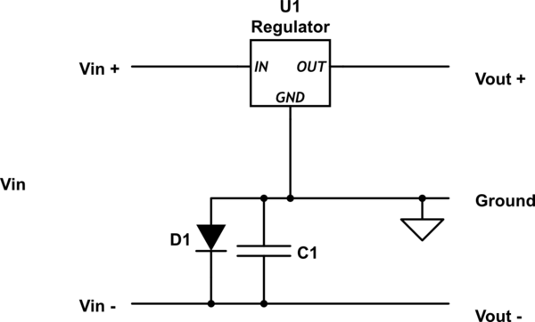
One "naughty" but entirely valid way of getting a small negative supply is to place a diode in the -ve return power supply lead.

System ground including all regulators etc are at the true ground = anode = most positive end of the diode and - 0.6V or so for a Si diode is at the cathode.

A Schottky diode gives a lower voltage, that may be enough here.

Place a decoupling capacitor across the diode.

Vin- will vary somewhat with overall system load and decoupling (here = C1) needs to be adequate to avoid secondary effects.

schematic

simulate this circuit – Schematic created using CircuitLab

\$\endgroup\$
4
  • \$\begingroup\$ That is very smart. However, I believe my friend was correct and I only realised why a while ago. The output voltage of the quarter bridge can indeed be negative, but both the positive and negative leads of the output voltage represent positive voltages relative to the system ground. I think the sentence I quoted before is concerned with negative voltages on AIN+ and AIN- individually(even though I still think the sentencing is misleading), not the differential of them. For example, I can feed each positive voltages relative to system ground even though their difference can be negative. \$\endgroup\$
    – Jamy codes
    Commented Apr 23, 2015 at 11:58
  • \$\begingroup\$ @Jamycodes - A problem is that you did not provide a circuit diagram and you used words which people took at face value. With circuits a picture can be worth an infinite number of words. You said eg " ... This means that I also need to think about the cases where I have negative output voltages from my bridge ..." and people, including me, assumed you meant relative to ground. I assume we assumed that this was for some reason that was inobvious to us but that you knew what you wanted. If you'd provided a diagram we would have seen we were wrong and that you didn't and advised you accordingly. \$\endgroup\$
    – Russell McMahon
    Commented Apr 23, 2015 at 21:32
  • \$\begingroup\$ I apologize if it seems that I have misguided you. Reading through the AD7730's datasheet, I was also confused. However, I have provided a link to my circuit diagram as well as a link to the AD7730's datasheet which I have quoted from, in my original post. If you click on the "AD7730L" and the word "Here" where I say "Here is a schematic of the circuit I would like to put together", you see that they are actually hyperlinks to the ADC's datasheet and my schematics of my circuit, respectively. Once again I apologize if I have misled you, but I genuinely appreciate your help. \$\endgroup\$
    – Jamy codes
    Commented Apr 25, 2015 at 9:29
  • 1
    \$\begingroup\$ @Jamycodes My apologies if I came across as overly grumpy. (Maybe more sleep would help :-) ). It's nice to know the whole spec at the start and ideally this can be done from what's in front of you without digging - but you did provide far more information that many people do. \$\endgroup\$
    – Russell McMahon
    Commented Apr 26, 2015 at 9:24

Your Answer

By clicking “Post Your Answer”, you agree to our terms of service and acknowledge you have read our privacy policy.

Not the answer you're looking for? Browse other questions tagged or ask your own question.