0
\$\begingroup\$

I am new to electronics and I am currently trying to learn a little more about how NPN and PNP transistors work. While doing some research, I stumbled across a circuit design called the Transformer-Less Push-Pull circuit. The schematic that describe such configuration is shown below:
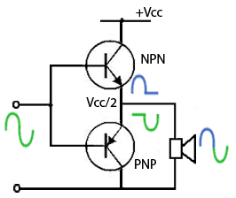
enter image description here

My problem is that I am trying to understand and reproduce the circuit above but I am just not being successful.

So my question is: Do the schematics shown above represent a real circuit (something that can be physically built and can work successfully) or is it just a sort of circuit analogy?

If the circuit diagram show avobe is not a real buildable working circuit, could someone please point me to some schematics that represents a real buildable Transformer-Less Push-Pull circuit? If at all possible, something simple would be best as I am just a beginner and will most likely get lost if the circuit is not relatively simple.

Thanks.

\$\endgroup\$
1
  • 1
    \$\begingroup\$ It's an illustration of the principal, and a rough one at that. See this very recent question for a real circuit and some good answers. \$\endgroup\$
    – tomnexus
    Commented Mar 9, 2015 at 20:33

3 Answers 3

3
\$\begingroup\$

This is a very simplified pic of the way that most audio power amp stages work. It is just trying to show that one of the two output transistors delivers current to the load at any time. In practice lots of other stuff would be needed to get this working, it's not a practical circuit as it stands.

\$\endgroup\$
2
\$\begingroup\$

it is not actually a real one you need two add (-VEE equal two VCC) to the emitter or use large capacitance in the output and input nodes otherwise pnp transistor has not appropriate bias

\$\endgroup\$
0
\$\begingroup\$

There's nothing wrong about the circuit at all. It's a class B push pull amplifier and will work fine if your ears are able to tolerate cross over distortion.

\$\endgroup\$
3
  • \$\begingroup\$ So are you saying that if I prototype the exact diagram shown above on a breadboard the circuit will function? I am only asking this because I tried that already (to the best of my abilities) and it does not work. So before I try again and burn another transistor I would like to make sure this actually works in real life! \$\endgroup\$
    – T555
    Commented Mar 10, 2015 at 0:21
  • 2
    \$\begingroup\$ The circuit above as it stands will not work as intended. The bottom legs of the PNP transistor and the speaker are both connected to "ground". The PNP cannot sink current from the speaker, that is, the green part of the waveform will not happen. \$\endgroup\$
    – rioraxe
    Commented Mar 11, 2015 at 1:33
  • \$\begingroup\$ @rioraxe I assumed it was an electrostatic speaker!!! You assumed it was a moving coil device LOL \$\endgroup\$
    – Andy aka
    Commented Mar 11, 2015 at 9:10

Your Answer

By clicking “Post Your Answer”, you agree to our terms of service and acknowledge you have read our privacy policy.

Not the answer you're looking for? Browse other questions tagged or ask your own question.