2
\$\begingroup\$

I have a voltage divider circuit that cuts an input voltage in half. The half voltage is fed into an ADC. I need this reading to be stable over temperature. The resistors are 100K, but I don't think this matters.

Do I need to use resistors that have a low temperature coefficient to have a stable reading?

Or, because the resistors are the same value and have approximately the same temperature coefficient, can I use standard resistors? The resistors will track each other over temperature and the midpoint will always be half the input voltage.

\$\endgroup\$
3
  • \$\begingroup\$ Can you provide some numbers, like +/- 1 mV over 0-100*C or +/- 20 mV over -35 to 125*C range. It will help to provide you with the best answer. \$\endgroup\$
    – Kellenjb
    Commented Jun 24, 2011 at 13:58
  • \$\begingroup\$ For this application: +/- 1mV over 0 to 50 degC \$\endgroup\$ Commented Jun 24, 2011 at 14:57
  • \$\begingroup\$ @Robert: that makes no sense w/o telling us the supply voltage. 3V? 5V? \$\endgroup\$
    – Jason S
    Commented Sep 2, 2011 at 11:43

5 Answers 5

5
\$\begingroup\$

Like Olin I was thinking of a resistor array. (Array being a big word for two resistors in a single package.) Firstly, being manufactured on the same process will give you a good matched value, and secondly being in the same package will make their temperatures also matching. At Vishay I found these "High Precision Thin Film Chip Resistor Arrays":

The networks provide 1 ppm/°C TCR tracking, a ratio tolerance as tight as 0.01 % and outstanding stability.

edit
Linear Technology has the LT5400 resistor array with the following specs:

0.01% Matching
0.2ppm/°C Matching Temperature Drift

Prices start at USD 3.49 quantity 1000, so that's pretty steep. For a couple of resistors, that is.

\$\endgroup\$
1
  • 3
    \$\begingroup\$ Agree. There is a special component for such task. If you dont require super high precision, then you can use 2 discrete resistors thermally coupled together. I used the thermal paste to completely fill the plastic box, containing a little board with array of discrete 2ppm resistors. It was cheaper than buying a matrix. I have got better than 24-bit resolution/certainty this way. \$\endgroup\$
    – user924
    Commented Jun 24, 2011 at 14:27
3
\$\begingroup\$

You should not assume two resistors will track just because they have the same specs. In reality, they will probably track somewhat, especially if they are from the same production batch, but you don't know that and shouldn't rely on that.

Either get resistors with low enough absolute temperature coefficient, or get resistors that are specifically matched. You can get multiple resistors in a single package that have matched temperature coefficient to well below their absolute temperature coefficients.

Look at manufacturers of more than just jellybean resistors, like Bourns, Vishay, etc.

\$\endgroup\$
2
  • \$\begingroup\$ You probably meant Bourns instead of Burr-Brown. \$\endgroup\$
    – B Pete
    Commented Jun 24, 2011 at 17:45
  • \$\begingroup\$ @B Pete: Oops, yes I did. Sorry for the confusion. \$\endgroup\$ Commented Jun 24, 2011 at 18:43
2
\$\begingroup\$

If the voltage range you are measuring at the output of the divider is between about 2 and 20 volts, you could use a "rail splitter" IC like this instead. It has an onboard precision-trimmed and temperature compensated resistor divider. The input has to be within the compliance range of the chip, however, hence the output voltage range restriction.

\$\endgroup\$
3
  • 3
    \$\begingroup\$ FYI, the resistor array is simpler, cheaper, smaller, consumes less power, more reliable and probably perform as well temperature-wise. Both 1ppm/°C and 0.01% ratio tolerance are hard to beat. "Output tolerance 1%", don't make me laugh ;-) \$\endgroup\$
    – stevenvh
    Commented Jun 24, 2011 at 14:44
  • \$\begingroup\$ @stevenvh - It's hard to beat those specs, but they certainly aren't cheap: mouser.com/Search/Refine.aspx?Keyword=vishay+pra100 \$\endgroup\$
    – MattyZ
    Commented Jun 24, 2011 at 17:52
  • \$\begingroup\$ Wow, that's pretty steep. For 2 tiny resistors. Forget cheaper then :-) \$\endgroup\$
    – stevenvh
    Commented Jun 25, 2011 at 13:32
1
\$\begingroup\$

Without giving us an error budget, e.g. max error at 25C, max error due to temperature, it's hard to say, but I'm assuming that max error due to temperature is more stringent than max error at 25C, because the latter can be calibrated out whereas the former cannot.

I would recommend just using a pair of 0.1% resistors if you can. Nowadays they're fairly inexpensive. Digikey sells 10K 0.1% 0603 resistors for 25c apiece that have 25ppm/C max tempco, with the price dropping to 10c apiece at high volumes. At that max tempco, even if one resistor has a +25ppm/C tempco and the other has -25ppm/C tempco, that will affect the output ratio of the divider by 0.0625% of fullscale -- at a 3V supply that's just under 2mV.

If you need tighter specs, get 10ppm/C resistors (more expensive: Mouser sells some from Xicon that are 75c apiece, dropping to about 20c apiece at very high volumes)

Or use an integrated matched pair of resistors meant for voltage dividers -- those are even more expensive, but you can get 5ppm/C tracking tempco from TT Electronics sold by Digikey at about $2.00 apiece dropping to 65c at very high volumes.

Or use a switched-capacitor voltage divider, and filter the heck out of it to get rid of switching noise.

\$\endgroup\$
0
\$\begingroup\$

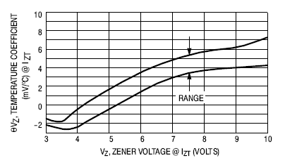
You can also look into using a zener diode in series with a PN junction. Zener diodes have a positive temperature coefficient that can largely cancel out the negative coefficient of a PN junction (like one in a BJT). This, of course still assumes that both components are at the same temperature, which may or may not be a valid assumption.

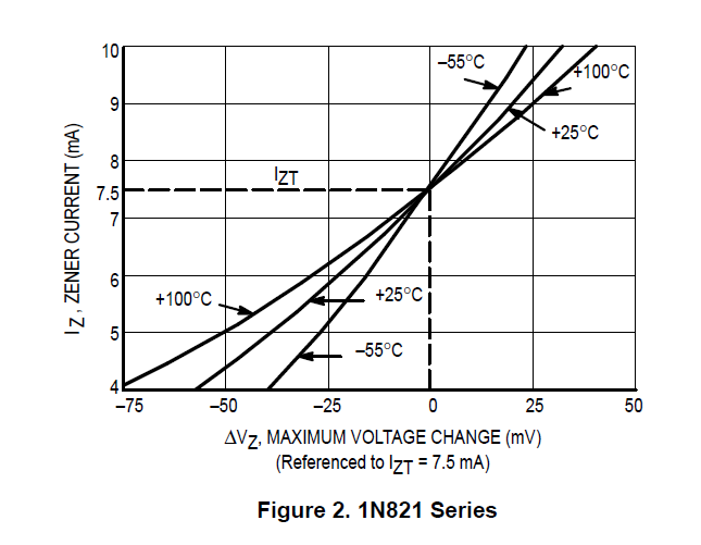
EDIT: @stevenh is probably thinking of this:

Temperature dependence of zener didoe from a 1N821

This is for a compensated zener diode, which has a silicon diode in series. Since the temperature coefficient varies with zener voltage, a 5.6V zener diode nicely cancels out the -2 mv/K of a silicon junction, creating the intersection in the above plot. An example of how the coefficient varies with zener voltage is below.

1N5333 Zener

\$\endgroup\$
3
  • \$\begingroup\$ TC for zeners varies with zener voltage. From what I remember from college (more than a few weeks ago) TC is lowest/zero at around 6V. \$\endgroup\$
    – stevenvh
    Commented Jun 24, 2011 at 14:34
  • 1
    \$\begingroup\$ BTW, how does this half a given voltage? \$\endgroup\$
    – stevenvh
    Commented Jun 24, 2011 at 14:36
  • \$\begingroup\$ that graph shows the voltage change vs reverse current. Try to find a graph of tempco vs voltage. You'll find that TC is negative for low voltage zeners, positive for higher voltage zeners, and zero for some value in between. IIRC this value is around 6V, but it could also be a bit lower. I'm not talking about temperature compensated, just zener. \$\endgroup\$
    – stevenvh
    Commented Jun 24, 2011 at 15:22

Your Answer

By clicking “Post Your Answer”, you agree to our terms of service and acknowledge you have read our privacy policy.

Not the answer you're looking for? Browse other questions tagged or ask your own question.