0
\$\begingroup\$

I have a gadget that does contain a 12V AC synchronous gear motor (2 Terminals) that i want to hack.

I want to supply the gadget with 12V DC (among other changes).

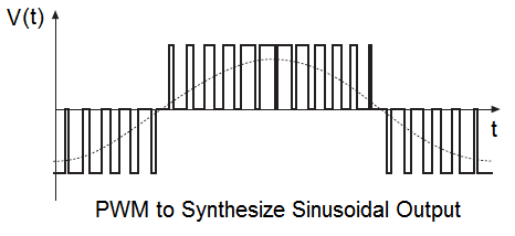
Up to now i use tiny AVR and a LB1641 motor driver to feed the motor with voltage of alternating polarity. Everything between 20 and 60 Hz with Pulses between 70% and 100% seems to work well.

L1  _____---_____---_____
L2  _---_____---_____---_

But the motor does not run as quiet as from the wall wart supply.

How can i transform the output of the Motor driver into something that is more pleaseant to the motor and my ears?

\$\endgroup\$
7
  • \$\begingroup\$ I am guessing that the problem lies in the square wave you are feeding it now. Try to put a... 1uF cap in parallel with your motor. Try also 100nF that might be better. \$\endgroup\$ Commented Apr 5, 2015 at 8:08
  • \$\begingroup\$ i tried the 100nF. with larger values i only have electrolytes that may not fit since the alternating polarities. \$\endgroup\$ Commented Apr 5, 2015 at 8:10
  • \$\begingroup\$ and yes i also assume that it is the square wave. i hoped the inductance of the motor and a small ceramic cap would smooth it out enough. but it does not seem to work. \$\endgroup\$ Commented Apr 5, 2015 at 8:14
  • \$\begingroup\$ low pass the square wave with an LC filter then. that's not really something I'm an expert of, sorry \$\endgroup\$ Commented Apr 5, 2015 at 8:23
  • \$\begingroup\$ me neither thatswhy i am asking ;) My knowledge mainly is in the digital domain. \$\endgroup\$ Commented Apr 5, 2015 at 8:43

2 Answers 2

2
\$\begingroup\$

Andy beat me to it. But anyway. I am a power electronics specialist - that sound you hear is the harmonic noise being caused by the square waves you are passing into the motor. It is physically damaging the motor and reducing efficiency by creating heating losses in the coils that don't create useful work, because they occur at other frequencies than where the work can happen.
enter image description here

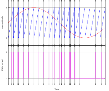
This is a basic two level sawtooth modulated PWM signal, just for reference.

See how the PWM signal is high much longer at the peak of the sinusoidal wave? That's where the magic is. If we divide it up into enough pieces and put well selected low-pass filter on it, it will practically turn into a pure sine wave.

Well, that's not really true. The voltage will still be blocky but the current waveform will have so much less distortion that you no longer need to worry about life-shortening harmonics and ear-grating noise.

You're already halfway there in many ways. If you're already generating a duty cycle now, with very little effort you will be able to find a library to bit-bang this kind of PWM signal output. Depending on the exact controller you are using, it may actually have an onboard function for this very thing.

\$\endgroup\$
2
  • \$\begingroup\$ Sorry Sean LOL!!! \$\endgroup\$
    – Andy aka
    Commented Apr 5, 2015 at 10:35
  • \$\begingroup\$ It's cool @Andy. We only end up having this problem when I have insomnia anyway. \$\endgroup\$
    – user39962
    Commented Apr 5, 2015 at 12:09
2
\$\begingroup\$

Use your AVR to modulate the pulse widths to mimic a sinewave instead of just hitting the motor with high-low pulses: -

enter image description here
(source: smps.us)

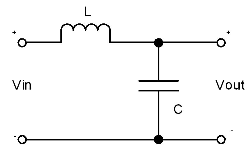
The PWM frequency you choose (maybe 1kHz or higher) may still cause a little noise but this is more easily filtered: -

enter image description here

The resonant frequency of the filter will need to be lower than your pwm switching frequency and higher than the ac frequency you are trying to smoothly reconstruct so if your pwm frequency is 1kHz and you want 70Hz to be reconstructed, choose a frequency for resonance that is logarithmically half way between the two ends (\$\sqrt{F_{SYNC}\cdot F_{PWM}}\$).

Resonance is at \$\dfrac{1}{2\pi\sqrt{LC}}\$

\$\endgroup\$
6
  • \$\begingroup\$ thank you for your easy to understand answer. What do you think how many sub devisions are neccesarry and how much resolution each division does require? are 16 subdivisions enough? The Wafeform of the original Supply looks a bit awkward. more like a Trapez. I guess i do not need that much resolution to exactly mimic a sinus in the upper parts so may be 3 bit are enough for 16 division. \$\endgroup\$ Commented Apr 5, 2015 at 20:00
  • \$\begingroup\$ The more resolution you have the better the sinewave and the less noise will be produced. I think the bottom line is try it i.e. do your best to get a neat piece of code working hard to achieve as high a resolution as possible. Hey don't break bones or get a hernia doing it, just try and achieve a good high pwm frequency and a moderate resolution on duy cycle. I think 3 bits are enough for amplitude resolution but maybe 16 recalculation points might be a little light of the mark. \$\endgroup\$
    – Andy aka
    Commented Apr 5, 2015 at 21:30
  • \$\begingroup\$ after a few years the thing fell back into my hands.and i'll try to finish this. I followed your suggestion with the varying duty cycle PWM phases and it makes a lot less noise but still more than the original 50Hz transformer. how do i have to put the filter into it? (circuits.datasheetdir.com/200/LB1641-circuits.jpg ) should be the filter between one of the motor outputs (2 or 10) and the motor or from one (or both) motor terminal(s) to the real ground? And what should be the values? the motor draws around 120mA. sinoidal freq. is variable from 25-50Hz. and 40 PWM cycles --> 1-2kHz \$\endgroup\$ Commented Feb 3, 2021 at 20:07
  • \$\begingroup\$ What pwm frequency are you using @vlad_tepesch. Take your time, there’s no hurry hehe \$\endgroup\$
    – Andy aka
    Commented Feb 3, 2021 at 20:42
  • \$\begingroup\$ 40 pwm cycles per complete sine. so 1kHz to 2 kHz \$\endgroup\$ Commented Feb 3, 2021 at 20:53

Your Answer

By clicking “Post Your Answer”, you agree to our terms of service and acknowledge you have read our privacy policy.

Not the answer you're looking for? Browse other questions tagged or ask your own question.