3
\$\begingroup\$

So I've been messing with Bipolar Junction transistors lately and I'm trying to really nail the concepts of designing circuits with these things cause I want to start using them in some of my circuits and maybe design my own amplifiers.

I've read online that if you want to make a temperature stable BJT circuit the easiest way is to place a resistor in the emitter junction and choose the resistance such that it's voltage when your circuit is stable is ~1.4V. I understand how it can accomplish this by being able to buffer changes in current due to the resistor proportionally changing it's voltage in response to the change in current, which thus inversely affects the base current and thus returns the circuit to the stable state.

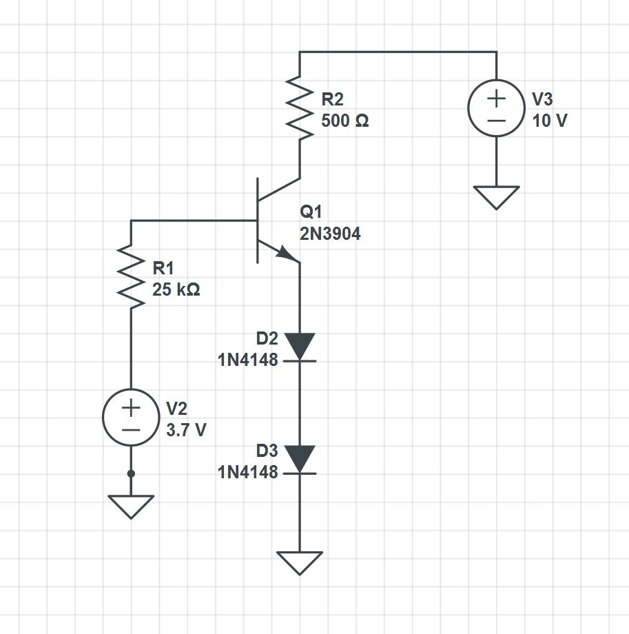
However, what if I were to use 2 silicon diodes instead of an emitter resistor? Assuming silicon diodes have a voltage drop of around 0.7V each, the diodes would have a bias of 1.4V just like when we were designing for the resistor. Would that maintain temperature stability like the resistor did? I've found conflicting reports online but I can't really see how the diodes could regulate changes in current besides just keeping a pretty stable voltage drop of 1.4V.

Here's an little circuit diagram of what I'm talking about, disregard the component numbers if that changes anything:
enter image description here

Now I do notice that in this example the voltage across the collector-emitter junction will be greater than half of the supply voltage.(assuming beta is ~100). I've read that there's a principle or something regarding this case,and I've seen a lot of people design their BJT circuits with the collector emitter junction to be half collector supply voltage. Does this half supply voltage thing also temperature stabilize the BJT?

Tl;Dr If your collector-emitter is at half supply voltage and there's no feedback/emitter resistors is the BJT temperature stable?

\$\endgroup\$
1
  • \$\begingroup\$ Thanks for fixing that for me Null, I was just about to do that. \$\endgroup\$ Commented Apr 9, 2015 at 12:56

2 Answers 2

3
\$\begingroup\$

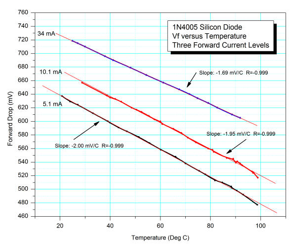
The base emitter (diode) junction is forward biased just like the two diodes you added and so, in effect, you get 3 lots of variations in junction voltage (for a given current) with temperature. The answer is no, I'm afraid not. Here's how a typical diode alters its voltage, for a given current, against temperature AND, the same is true of the base-emitter junction: -

enter image description here

Three different operating currents produce surprisingly similar slopes that tell you that a diode's forward voltage drop largely reduces at 2mV for a one degC rise in temperature. Resistors don't do this of course and you also have to consider that a diode has got a very low dynamic resistance once biased at some arbitrary operating point of a few hundred micro-amps upwards. This dynamic resistance is lower than a typical emitter resistor: -

enter image description here

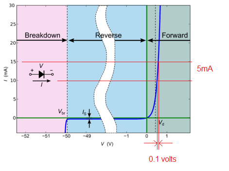
Look at the right hand portion of the diagram - I've drawn two horizontal lines at 10mA and 15mA with the corresponding forward voltage drops. The difference (deltas) allows you to calculate the dynamic resistance = 0.1 volts / 5mA = 20 ohms i.e. probably less than the emitter resistor you might choose BUT, it changes with current so you get more gain than you bargained for (gain harder to define) and high signal non-linearity (distortion).

Setting the operating point of the collector at about half the supply voltage is useful to be able to obtain the maximum swing of signal (in terms of Vp-p) at the collector i.e. one side of the output signal doesn't clip much earlier than the other. There are subtleties here but that's the basic rule to maximize output amplitude and no, neither does this affect temperature stability.

Either use negative feedback (with care) or use an emitter resistor to lower the gain of the common emitter amplifier.

\$\endgroup\$
2
  • \$\begingroup\$ Thanks, I had a sneaking suspicion it was something like this but you really cleared it up for me. Just to clarify though, so having the diodes like this will in fact make it LESS temperature stable since,like the BJT, the diodes also want increased current wrt temperature? \$\endgroup\$ Commented Apr 9, 2015 at 13:31
  • \$\begingroup\$ Correct. Plus the non-linearities of the diode (current versus voltage applied) make an amplifier produce a more distorted signal than a transistor with a regular emitter resistor. \$\endgroup\$
    – Andy aka
    Commented Apr 9, 2015 at 13:37
6
\$\begingroup\$

You have a number of misconceptions. Your basic understanding of how a emitter resistor provides negative feedback and thereby stability is correct, but some of the so-called "rules" you quote are just silly beliefs.

I can't even guess what archaic religious ritual derived the value of 1.4 V for being across the emitter resistor. That's just nonsense.

The base-emitter junction looks like a diode to the circuit driving it. As with regular diodes, a small change in voltage can cause a large change in current. Or conversely, the diode voltage varies little over a large change in current. Therefore, even a little voltage change on the emitter can make a big difference to the base and therefore collector currents of a transistor when the base voltage is being held fixed. The emitter resistor value in this usage is a tradeoff between generating enough voltage to provide meaningful feedback, but dropping little voltage to not get in the way of the intended operation of the circuit and to not dissipate significant power.

For example, the final output stage of a audio amplifier that drives a 8 Ω speaker might only use 1 Ω or maybe even just 100 mΩ emitter resistors. At 1 A, even the 100 mΩ emitter resistor will cause a 100 mV offset in the base drive. 100 mV across the B-E junction can make a large difference in base and collector current.

The diodes you show in series with the emitter actually make things worse. Remember that the voltage across a diode changes little with the current thru it. That's opposite of what you want. As the current thru the resistor gets too large, you want whatever is in series with the emitter to drop more voltage, thereby decreasing the B-E voltage.

Another problem with diodes is that the voltage across them at the same current goes down with temperature. This is also backwards of what you want. As the current gets higher, the diodes will dissipate more power, and decrease their voltage in response. This causes more current, which makes them hotter, which causes even more current, etc. This is called thermal runaway, and is a issue you have to consider when designing BJT circuits that handle significant power. Note that the B-E junction has the same temperature characteristics, so a BJT can have thermal runaway on its own, even without this being helped along by additional diodes in series with the emitter.

It can be useful to use diodes in the base drive part of the circuit to compensate for the B-E voltage of the transistor. That, together with a properly chosen emitter resistor can be a useful way to bias a BJT.

\$\endgroup\$
3
  • \$\begingroup\$ Thanks,Olin. I knew it wasn't really a rule set in stone but I did see a few guides that made it look easier for basic design purposes which is why I've been using it. This was out of some older material though. Would you suggest me use another number instead for the emitter resistor voltage while designing or do you just let the voltage across the emitter resistor fall out and get calculated based on other assumptions you make? \$\endgroup\$ Commented Apr 9, 2015 at 13:28
  • \$\begingroup\$ @Elect: You don't start with a fixed voltage you want across the emitter resistor. You have to look at all the tradeoffs, including how much operational voltage you can spare to drop across the emitter resistor, how much power it dissipates, what other bias point feedback you have, etc. There is no simple rule like what you want. \$\endgroup\$ Commented Apr 9, 2015 at 13:32
  • \$\begingroup\$ Oh that makes sense Olin, I haven't even begun to factor power dissipation into any of this yet as I'm just making and designing simple circuits. Thanks again! \$\endgroup\$ Commented Apr 9, 2015 at 13:36

Your Answer

By clicking “Post Your Answer”, you agree to our terms of service and acknowledge you have read our privacy policy.

Not the answer you're looking for? Browse other questions tagged or ask your own question.