7
\$\begingroup\$

Overview-

I'm making a bank of analog sine wave oscillators and I'm interested in keeping the design compact.

I've started by making a Wien Bridge oscillator. As I'm working from a single power supply and I'm trying to keep the design small, I've been using the LM386n-1 IC.

I'll be using the oscillators to do some additive audio synthesis, maybe some FM and I'll probably need some of the oscillators as LFOs.

My questions are-

Is this a suitable approach for making a compact analog sine wave oscillator?

Also, how would you suggest I control the frequency, which component value should be changed to achieve this? - I've tried messing with all the resistors to change the pitch, but they all seem to be interdependent.

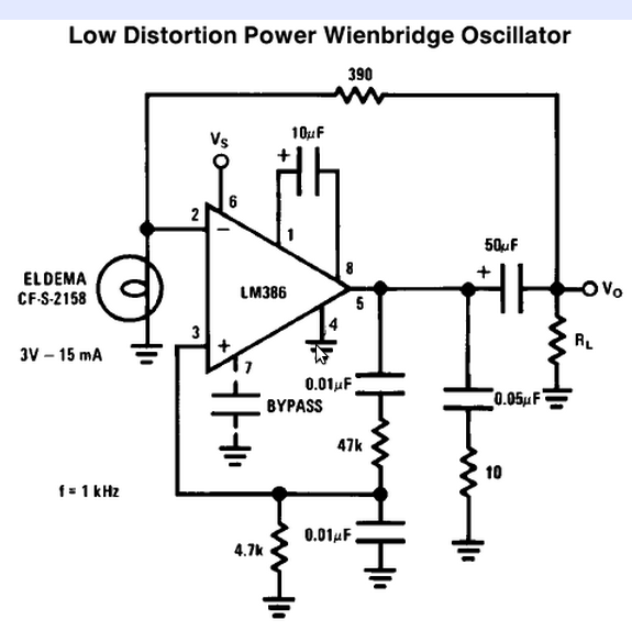
Here is the circuit I've been working from, it's from the National Semiconductor LM386 Low Voltage Audio Power Amplifier datasheet-

wien bridge LM386

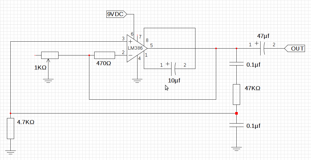
And this is what my implementation looks like, I don't have a suitable incandescent bulb so I've just replaced it with a 1KΩ pot. I'm still not sure what I'll use in the final circuit as AGC, suggestions are welcome.

my wien bridge LM386

\$\endgroup\$

6 Answers 6

20
\$\begingroup\$

This doesn't answer what you asked, but I think relevantly addresses the problem.

Nowadays doing this in analog is silly except perhaps for some very specialized or high frequency applications. You mentioned this is a audio application, so I can't imagine a good reason for all the analog. Your first sentence mentions you want a whole bank of these things, and you want the design compact. The analog approach will definitely not be compact. Another problem with the analog approach is that the frequencies and amplitudes will drift.

A much better way to do this is to generate all the sine waves in a processor and add them up digitally. They can all use the same 1/4 wave sine table, just index into it at different increments per sample to get the different frequencies.

This is well within the capability of even low end DSPs, like the Microchip dsPIC line. A dsPIC33F sounds like a good fit. At 40 MIPS, you have 1000 instruction cycles every sample at 40 kHz sample rate. That's a lot, and will allow lots of different sines to be added each sample. The DSP multiply-accumulate hardware will allow each contribution to be added with its own gain easily.

Digitally derived signals like that won't drift in frequency or amplitude, and will have better signal to noise ratio. With 16 bit numbers you get 96 dB. That's doable in analog if you're careful. However, the accuracy of the digital signal will be far greater. There is no chance at all the analog sine generators can be within 1 part in 65000 each sample just due to amplitude unpredictability alone. The frequency of the digital signals can also be set very accurately, and the digital sine synthesizer won't need a few cycles to stabalize before its output is what you expect.

Edit: Clarification on Sine Generation

I see some drawbacks of table lookup sine generation mentioned in other answers that are incorrect, so I'm adding more clarification of the method here. Two objections were brought up, accuracy and frequency resolution.

First let me explain the normal structure of a sine lookup. Note that a sine wave is four-way symmetric. You therefore only need to store 1/4 cycle. The basic first quadrant waveform is repeated either reversed, negated, or both in the remaining three 1/4 cycles. A nice trick to make this easy is to express the angle such that a full circle is a power of two, preferably using the whole word of whatever machine is running the code. That means angle additions and subtraction wrap around the circle automatically without explicit code for that purpose if you do the angle math in unsigned integer arithmetic. This representation also makes the lookup into the 1/4 wave table very easy.

The two high bits of the angle indicate the quadrant, so only the remaining lower bits are used to index into the table. If the highest angle bit is set, then the table result is negated. If the next highest bit is set, then the table is indexed backwards. That is as simple as complementing the remaining low bits before using them as the index. The table need not be the size such that all the low bits can be used as the index. For example on a 16 bit machine like a dsPIC, it would be natural to use 16 bits for the angle. That leave 14 bits to index into the table, which would be a very large table. Typically, and in this case, such a large table is not needed. A reasonable size might be 1024 segments, which would use 10 index bits. The remaining 4 index bits (in this example) can either be ignored or used to interpolate between adjacent entries. The table would actually have 1025 entries, which means 1024 segments. A sine wave approximated with 4096 (the table gets used 4 times over the whole sine wave) steps would be quite good. If the extra bits are used to interpolate between adjacent table entries, it's even better. Imagine a sine wave approximated with 4096 linear segments per cycle. It would be very difficult to see any error.

As for accuracy, do the math. A sine wave changes most rapidly at zero angle, so it's easy to compute the worst case error from just a dumb lookup into a 1024 point table. The first table value would be 0, and the second sine(Pi/2048) = .00153. The worst case error is therefore half that, or .000767. That amounts to a signal to noise ratio of 62 dB, and that is just from picking a table value without interpolation. Using the remaining 4 index bits to interpolate increases the signal to noise ratio to 86 dB. If that's not good enough, use a wider number for the angle and interpolate using the extra bits.

Frequency resolution is also not a issue. Apparently some are thinking the angle increment per sample must be a multiple of the angle step per table entry. That's not true at all. Using just a 16 bit angle and a 1024 segment table already gives you 16 times more angle resolution than each table entry. In practise I'd probably use two words (32 bits in this example) for the angles and angle increments. That provides very high frequency resolution, and also gives you more interpolation bits to get the signal to noise ratio up. At a 40 kHz sample rate, a 20 Hz tone (the worst case) would require a angle increment of 1/2000 circle per sample. That's one part in 33 is using 16 bit angles. That alone could be good enough for many applications. If using a 32 bit angle, the frequency resolution at 20 Hz is over 1 part in 2 million.

So let's not dismiss lookup-based sine generation in firmware so quickly. At least let's not dismiss it for the wrong reasons. Note that none of the things I described would be difficult for a dsPIC to do. This includes interplation since a dsPIC can do a 16 x 16 into 32 bit multiply in a single instruction cycle.
\$\endgroup\$
13
  • \$\begingroup\$ You make a compelling argument, the reason for trying to make analog oscs is because people have been requesting them. I've asked in the past on this forum and people have talked about wanting a digital controlled analog synth. \$\endgroup\$
    – Jim
    Commented Jul 8, 2011 at 11:49
  • 3
    \$\begingroup\$ I wonder if people want the drift and inaccuracies, and if so, should they just be programmed into a digital sine wave generator? hummm, I'm starting to change my mind about using analog for this application. \$\endgroup\$
    – Jim
    Commented Jul 8, 2011 at 11:51
  • \$\begingroup\$ "and will have better signal to noise ratio" ... assuming you implement it correctly \$\endgroup\$
    – endolith
    Commented Jul 8, 2011 at 14:12
  • \$\begingroup\$ Cheers Endolith, That's given me another idea for the analog emulation- fake noise :) \$\endgroup\$
    – Jim
    Commented Jul 8, 2011 at 14:25
  • 3
    \$\begingroup\$ @Jim - If you create the noise with a Linear Congruential Generator (LCG) with a too short cycle length you get a motorboating sound, which surely will convince them that it's analog. \$\endgroup\$
    – stevenvh
    Commented Jul 8, 2011 at 14:35
7
\$\begingroup\$

The reason for using a small incandescent lamp is that it has a positive temperature coefficient (PTC), which the oscillator needs to stabilize the amplitude. The potmeter won't do.
The negative feedback resistor should be at least twice the resistance of the PTC.

The oscillator frequency is determined by the two resistors and two capacitors on the non-inverting pin, and the schematic seems to have an error: both resistors should be equal (either 4k7 or 47k), as should the capacitors. The frequency is

\$f = \dfrac{1}{2 \pi R C}\$

So you can control the frequency by using a stereo potmeter for the resistors. Both channels should have good tracking.

Following suggestions I made a separate answer about DDS, so the comments about it actually refer to that answer.

\$\endgroup\$
9
  • \$\begingroup\$ I'm aware of this phenomena, I've got the pot so I can produce a sine at a fixed freq. I intend to use a component with a PTC- just probably not an incandescent lamp. Thanks for the equation and tips, I'll check them out. \$\endgroup\$
    – Jim
    Commented Jul 8, 2011 at 11:32
  • 1
    \$\begingroup\$ A DDS chip is a nice solution, but I wouldn't dismiss doing it all in a micro so quickly. The OP did say compact was important. Also, a 1000 interval 1/4 sine lookup table will be very accurate. Even more accurate with interpolation, but with 1000 intervals may not be necessary for many applications. The table increment per sample doesn't need to be integer either. You can use fraction bits to get arbitrary frequency accuracy. \$\endgroup\$ Commented Jul 8, 2011 at 12:14
  • 1
    \$\begingroup\$ @Jim - (Is this gonna cost me my points? ;-)) The 9851 generates just one signal, so may be an expensive solution if you want a complete bank of sine generators. Jesper's MiniDDS may be more appropriate. \$\endgroup\$
    – stevenvh
    Commented Jul 8, 2011 at 12:34
  • 2
    \$\begingroup\$ The DDS should be a separate answer so people can vote it up or down independently \$\endgroup\$
    – endolith
    Commented Jul 8, 2011 at 14:11
  • 1
    \$\begingroup\$ @endolith - done! (what do you mean: vote down??? :-)) \$\endgroup\$
    – stevenvh
    Commented Jul 8, 2011 at 14:27
3
\$\begingroup\$

A few people suggested that I add a separate answer about the DDS. So I extracted it from my other answer.

Olin's answer is a sensible one: this is the digital age. Like he says your signal will be much more stable (crystal precision), but using a microcontroller is not the solution; your sine lookup table is fixed, and the frequency steps may be too coarse.
A better solution is DDS, Direct Digital Synthesis. This is often done with special DDS ICs, like AD9851, and allows for a very high level of frequency control (depending on the clock up to milliHertz resolution). You'll need a microcontroller to control the sysnthesizer, so it won't be the most simple application, nor the cheapest. But there are good alternatives: Jesper Hansen designed a simple DDS implementation based on an AVR controller.

\$\endgroup\$
2
  • \$\begingroup\$ There is no need for the frequency steps to be coarse. Of course the sine lookup table is fixed, but that in itself is not a problem. I think there is some misunderstanding of the lookup method, so I added more detail on it in my answer. \$\endgroup\$ Commented Jul 8, 2011 at 19:30
  • \$\begingroup\$ @Olin - Yes, you're absolutely right (of course! :-)). Thanks for your efforts to explain in detail. \$\endgroup\$
    – stevenvh
    Commented Jul 9, 2011 at 16:39
2
\$\begingroup\$

I would second (or third) Steven's and Olin's arguments. Whilst it is perfectly possible to build an analog synthesiser it poses significant challenges. Top of the list is temperature stability - having to frequently retune oscillators is no fun and I write from personal experience in building a traditional (subtractive) synthesiser with just two oscillators some years ago.

And if you're keen on additive synthesis, forget it! You will be juggling far too many oscillators and you won't be able to keep up with the frequency drift. Now I know some people still prefer analog synthesisers to digital for their fat, free-phase sound but I'm not convinced.

There is a guy called Doug Curtis who founded a company called Curtis Electromusic Specialities in 1979 to produce dedicated ICs for the traditional functions of VCOs, VCFs etc and these probably extended the life of analog synthesiser designs by a few years by being far less prone to drift (and making designs cheaper), but even he succumbed to the digital revolution by 1988. There is still old stock of his chips around which go for premium prices on eBay!

On the subject of FM sound synthesis, this was the subject of my BSc dissertation in 1981 and whilst I managed to develop an analog FM sound 'engine', my conclusions were that it couldn't match a digital synthesis engine - and that was 30 years ago!

\$\endgroup\$
8
  • \$\begingroup\$ Hey, somebody else who remembers Curtis Electromusic Specialties! Gee, Mike, you're old! :-) \$\endgroup\$
    – stevenvh
    Commented Jul 8, 2011 at 13:41
  • \$\begingroup\$ I guess I'll have to make my digital oscillators with an analog emulation mode, so they phase and drift about- that should keep the puritan audiophiles happy. Thanks for your input. \$\endgroup\$
    – Jim
    Commented Jul 8, 2011 at 13:46
  • 1
    \$\begingroup\$ @Jim - DDS works with a phase accumulator, and I think most DDS ICs will have a phase modulator (the AD9851 does), which adds an offset to the phase accumulator. So they have built-in phase modulation. \$\endgroup\$
    – stevenvh
    Commented Jul 8, 2011 at 14:09
  • 1
    \$\begingroup\$ @Jim: They may just be impressed by the word "analog" more than any features it has. Just throw some tubes in it that don't do anything and they'll say it has "a really warm tube sound". \$\endgroup\$
    – endolith
    Commented Jul 8, 2011 at 14:16
  • 1
    \$\begingroup\$ @endolith lol, I guess! damn analog audiophiles- I wonder how many of them would pass the coke / pepsi challenge? not many I suspect. \$\endgroup\$
    – Jim
    Commented Jul 8, 2011 at 14:23
1
\$\begingroup\$

Here is a software DDS approach I've used, based on Jesper Hansen's MiniDDS, which generates a sine wave up to 200 kHz or so. Filtering would be useful in some applications.

\$\endgroup\$
4
  • \$\begingroup\$ Thx Leon, nice project, like the home made PCB too- it looks great in white :) \$\endgroup\$
    – Jim
    Commented Jul 8, 2011 at 13:56
  • \$\begingroup\$ That's a cheap paper composite material I use because it's much easier to cut and drill than FR4. \$\endgroup\$ Commented Jul 8, 2011 at 14:26
  • \$\begingroup\$ Nice, I get a similar type of board from my local store, but it comes in a nasty yellow. And you're right- FR4 is a nightmare to cut in comparison. I just cut the paper composite with a carpenters knife, it's much more DIY friendly. \$\endgroup\$
    – Jim
    Commented Jul 8, 2011 at 14:41
  • \$\begingroup\$ @Leon, @Jim - that type of board can also have its problems. Read and shudder. \$\endgroup\$
    – stevenvh
    Commented Jul 8, 2011 at 16:26
1
\$\begingroup\$

Sorry this is so late. The bulb is there to provide amplitude stability to the oscillator to stop the feedback running away. As the current through the bulb increases it get hotter. As the bulb's filament heats up its resistance increases and the feedback decreases. It can quickly stablise the circuit and can be very effective.

\$\endgroup\$

Your Answer

By clicking “Post Your Answer”, you agree to our terms of service and acknowledge you have read our privacy policy.

Not the answer you're looking for? Browse other questions tagged or ask your own question.