0
\$\begingroup\$

I'm an IT guy, but have lately started working more and more "on the edge" as we say, so close to the real world and with low level sensors. I'm currently building a liquid throughput sensor and reading it with a raspberry pi to send it to a server.

These are the specificiations for the sensor:

  • 2500Imp/L at 20°C
  • 0,05 - 3L/min
  • using a Hall sensor principle

The link to the product would be this FCH-m-POM-LC

I can read the pulses using a pull up resistor at the signal with 3.3V and 2kOhm. But there are two problems:

  • when I squeeze 60ml through a syringe into the sensor I get about 300pulses == to 120mL with a deviation of about 10ml (tried 10 times) did I calculate something wrong? I'm listening for "falling edges" so I count every time the voltage drops to 0V
  • It often doesn't work and if it works, it does so best when in a horizontal axis, so reading pins up, liquid in/out on one level. Is this normal for these flow sensors?

as you might be able to tell I'm used to software, not hardware so treat me like a first year engineering student if you want.

I'd greatly appreciate your help! Greetings from Germany

P.S. its for a cow milking battle where we want to have several participants milk a fake cow and see who's the fastest. We want to measure on a 1/10sec precision and visualise the data throughput/second for 120seconds

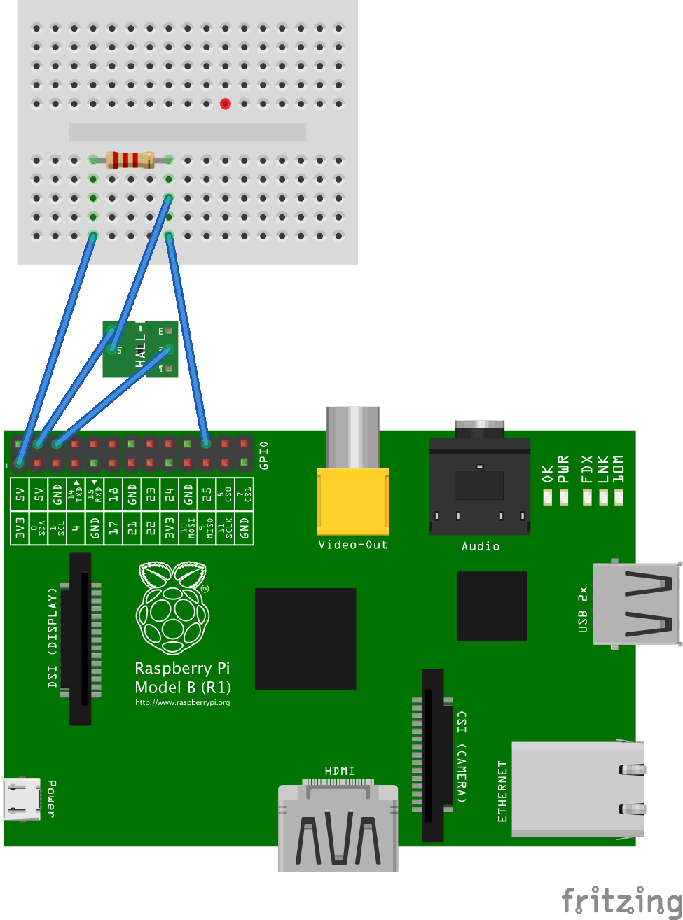
I created an image of my setup. however I used 5x 10k Ohm resistors in parallel since I don't have 2.2kOhm Resistors. enter image description here
\$\endgroup\$
4
  • \$\begingroup\$ Are you supplying it with 5V? \$\endgroup\$ Commented Apr 24, 2015 at 12:21
  • \$\begingroup\$ Are you counting both the rising and falling edges of the square wave as pulses? Capacitively coupling the square wave? A circuit diagram always helps. Do you have a 'scope? \$\endgroup\$ Commented Apr 24, 2015 at 12:34
  • \$\begingroup\$ I'm counting only falling edges (since its a pull-up resistor) GPIO.wait_for_edge(18, GPIO.FALLING) #python code \$\endgroup\$ Commented Apr 24, 2015 at 12:54
  • 1
    \$\begingroup\$ I'm thinking I have to integrate some form of "bouncing correction" as described here ..maybe sleep 8-10ms after each edge interrupt so no bouncing is caused? may such a sensor have this bouncing issue as buttons do? \$\endgroup\$ Commented Apr 24, 2015 at 13:06

3 Answers 3

1
\$\begingroup\$

I guess it's not an electronic problem. The sensor contains a small impeller which is set into rotation by the liquid. If there is air inside the system, the impeller may not start rotating as intended, or not at all.

Also, if the flow stops abruptly (as it does when you use a syringe), the impeller may still rotate for a while, resulting in a too high measured volume. This effect of course is amplified when there's air in the system.

I'm not sure if this sensor is the right thing for your project. May be, a scale below the bucket is better? A household scale is available at pearl for 10€. I'm sure you can still replace the internal electronics by your own, just leaving the sensor and mechanical support.

(greetings from Germany)

\$\endgroup\$
1
  • \$\begingroup\$ well the problem is, the whole concept builds on "live performance measuring" since its a SAP Hana showcase (live in memory database calculations) and the bucket concept with the scale etc. would result in too much timelag. we want to pull on the tit and see the results almost immeadiately. With a bucket there would be too much spray, measurements would be going up and down a bit before settling etc. \$\endgroup\$ Commented Apr 24, 2015 at 13:04
0
\$\begingroup\$

Troubleshooting is pretty hard remotely- especially with this sort of thing.

Turbine and paddle wheel flowmeters are not great in repeatability (friction causes errors, especially at low flow rates, and it's not necessarily consistent), and that goes exponentially for cheap ones.

Suggest you test the software with an independent signal source. You can start with a bench-top signal generator at various different frequencies. Go well above the maximum average because the frequency will vary wildly as spurts of 'milk' pass through. Presumably you're using an interrupt-driven architecture or you'll probably be missing edges. There are plenty of things that can go wrong with the software, even so.

Look at the input signal with an oscilloscope and verify it looks reasonable. As @geometrical suggests, check that the power supply for the sensor is within the recommended operational range, and that the output signal is in the proper range for the Rpi. If any of those are not correct, fix them first.

\$\endgroup\$
4
  • \$\begingroup\$ Hey. I give 5V to the Vcc Input of the sensor which has a working range of 5-24VDC. I use 3.3V to pull up the Signal, since the Input of the RPI can only handle that much Volt without breaking.Appearently the Sensor has +-0,5% error for repeatability and +-2% for accuracy. Those values are totaly fine for me but what I'M seeing is 100% more edges than expected + 10% error. The software is tested separately, I mocked the GPIO interrupts with simple keyboard presses and made 1 keypress = 1 pulse \$\endgroup\$ Commented Apr 24, 2015 at 12:52
  • \$\begingroup\$ Sounds reasonable- is it a well-respected sensor maker? If so, they should have curves showing the accuracy vs. flow rate, not just a single number (at the best possible constant flow rate). The accuracy will decrease to zero at low flow rates (probably including the lower end of the quoted measurement range). If it's a no-name offshore thing, then I'm afraid that the accuracy numbers may be "somewhat" on the "optimistic" side. \$\endgroup\$ Commented Apr 24, 2015 at 13:39
  • \$\begingroup\$ The company is called Bio-Tech, they seem somewhat alright, however I have no idea how a well-respected company for sensors should look like. I know Bosch thats about it :-D there's no curves, just the numbers.. \$\endgroup\$ Commented Apr 24, 2015 at 13:55
  • \$\begingroup\$ From their website, Bio-Tech seem like a responsible company. Other than the obvious suggestion to talk to their support folks about the discrepancies you believe you are seeing (2:1 is not small), I do think you should test the micro with a signal generator up to XX Hz where XX is much higher than the average flow. \$\endgroup\$ Commented Apr 24, 2015 at 14:09
0
\$\begingroup\$

First, there is no sensor in the list at the link you provided which comes close to matching your specs. All of the 3 liter models with pull-down output stages have sensor outputs at roughly 10,000 impulses per liter. Furthermore, none of them have a minimum flow rate of .05 L/min.

There are several units, 971478089, 96103114 and 97138031, which have minimum rates of .05 L/min , but they are 6 liter max rates, not 3. And I strongly suspect that you have a model 971478089 with a nominal output of 5,000 imp/L, which will give you the counts you observe. The other two have outputs of 2500 imp/L.

\$\endgroup\$

Your Answer

By clicking “Post Your Answer”, you agree to our terms of service and acknowledge you have read our privacy policy.

Not the answer you're looking for? Browse other questions tagged or ask your own question.