2
\$\begingroup\$

I was given the task to make a new version of a board which have this little contraption for RS485 termination resistors:
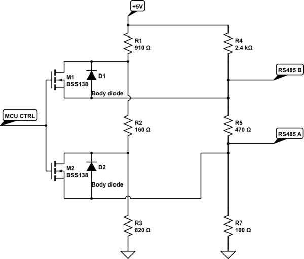
schematic

simulate this circuit – Schematic created using CircuitLab

My question is, does this really work? I my concern is that the body diodes will mess things up.

I have seen that some manufacturers offer RS485 driver chips with a termination resistor that is possible to enable/disable, however theese doesn't match the required resistance in my application.

\$\endgroup\$

2 Answers 2

0
\$\begingroup\$

weird! without understanding the broader context, I don't know why you'd want 'dynamic' control over the termination & biasing resistors, but I guess someone had a good reason for it.

in 'ideal conditions' when there's little ground differential between each end of the line, this should work - the MOSFETs bring in the 910/160/820 resistors, and get you a typical ~120R termination & reasonable-looking bias resistors.

but one of the reasons for using RS485 is to tolerate differences in the ground potential between endpoints! '485 transceivers will have specs like "InputA/B can be +12 to -7V w.r.t. Gnd". If that happened to be the case, then yeah, not only will the body diodes come into circuit & make for 'fun', but even the gate voltages will shift too. Maybe that isn't a factor in your application, though.

\$\endgroup\$
1
\$\begingroup\$

I'm looking for a similar solution and I found this of TI proposes this reference design Controller Area Network (CAN) with Selectable Termination Reference Design.

\$\endgroup\$
1
  • \$\begingroup\$ Please post relevant information in the post so when the link goes down people your answer will still be valid \$\endgroup\$
    – Voltage Spike
    Commented Mar 20, 2018 at 17:46

Your Answer

By clicking “Post Your Answer”, you agree to our terms of service and acknowledge you have read our privacy policy.

Not the answer you're looking for? Browse other questions tagged or ask your own question.