my goal is to use Arduino with 2 proximity probe sensor to achieve some output like orbit plot for a shaft mounted on a bearing

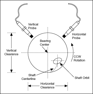
the system

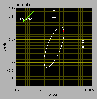
the orbit plot
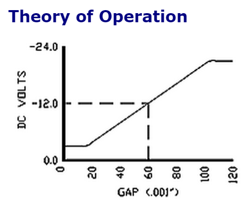
the proximity probe sensor has a negative voltage output from 0 to -24 volt, as the arduino accepts voltage only in the range of 0 to 5 volt,so I decided to use op-amp to invert and to scale down the voltage so instead of being in the range 0 to -24 v, it will be 0 to 5 v
worth mentioning that, the output of the proximity probe has 2 components: 1- DC out put that determines the position or the GAP 2- AC component on the top of that DC voltage to determine the vibration

my questions are :
1- how can I get to separate the ac from the dc component ? I mean like I want to use the DC value to determine the GAP and the AC to determine the vibration, should I use AC coupling ?
2- is this configuration and the whole idea applicable and reliable ? I mean using arduino and then using the op-amp invert and to scale down the voltage ? is there a better and cheaper way to do this?
please correct if I am mistaken at any point, sorry this is my first experience with this proximity probe thing, and some questions may seem silly and this is what I managed to get after a lot of searching
