I'm trying to establish communication between Atmel Atmega32U4 (used in Arduino Leonardo) on MCU PCB and TI DAC8552 on PSU PCB via isolated SPI link. For isolation I'm using Silicon Labs Si86xx digital isolator which can go up to 150MHz. While everything works as expected WITHOUT isolator I got a quite strange results when isolator is put in between MCU and DAC device. For testing is used very simple Arduino sketch which sending in infinite loop two values to the DAC each last 20ms:
#include "SPI.h"
int DAC2_SELECT=5; // uncomment this line if Arduino board is used instead of PSU MCU board
int IO_EXPANDER2=6; // uncomment this line if Arduino board is used instead of PSU MCU board
int ADC2_SELECT=13; // uncomment this line if Arduino board is used instead of PSU MCU board

int var=0;

void setup()
{
  // Deselect devices that share same SPI bus on the PSU post-regulator board
  pinMode(ADC2_SELECT, OUTPUT);
  digitalWrite(ADC2_SELECT, HIGH); // Deselect ADS1120
  pinMode(IO_EXPANDER2, OUTPUT);
  digitalWrite(IO_EXPANDER2, HIGH); // Deselect MCP23S08

  // Initialize DAC8552
  pinMode(DAC2_SELECT, OUTPUT);
  SPI.begin(); // wake up the SPI bus.
  SPI.setBitOrder(MSBFIRST);
  SPI.setDataMode(0);  //CPOL=0, CPHA=0
  // SPI.setClockDivider(SPI_CLOCK_DIV16); // Slow down SPI clock speed to 1MHz for testing purpose

  digitalWrite(DAC2_SELECT, LOW);
  SPI.transfer(B00100100); // Write to Data Buffer B
  SPI.transfer(0x99); // send first byte
  SPI.transfer(0x99);  // send second byte
  digitalWrite(DAC2_SELECT, HIGH); // Deselect DAC
}

void loop()
{
  digitalWrite(DAC2_SELECT, LOW);
  SPI.transfer(B00010000); // Write to Data Buffer A
  SPI.transfer(0x20); // send first byte
  SPI.transfer(0x00);  // send second byte
  digitalWrite(DAC2_SELECT, HIGH); // Deselect DAC
  delay(20);

  digitalWrite(DAC2_SELECT, LOW);
  SPI.transfer(B00010000); // Write to Data Buffer A and activate channel A
  SPI.transfer(0x80); // send first byte
  SPI.transfer(0x00);  // send second byte
  digitalWrite(DAC2_SELECT, HIGH); // Deselect DAC
  delay(20);
}
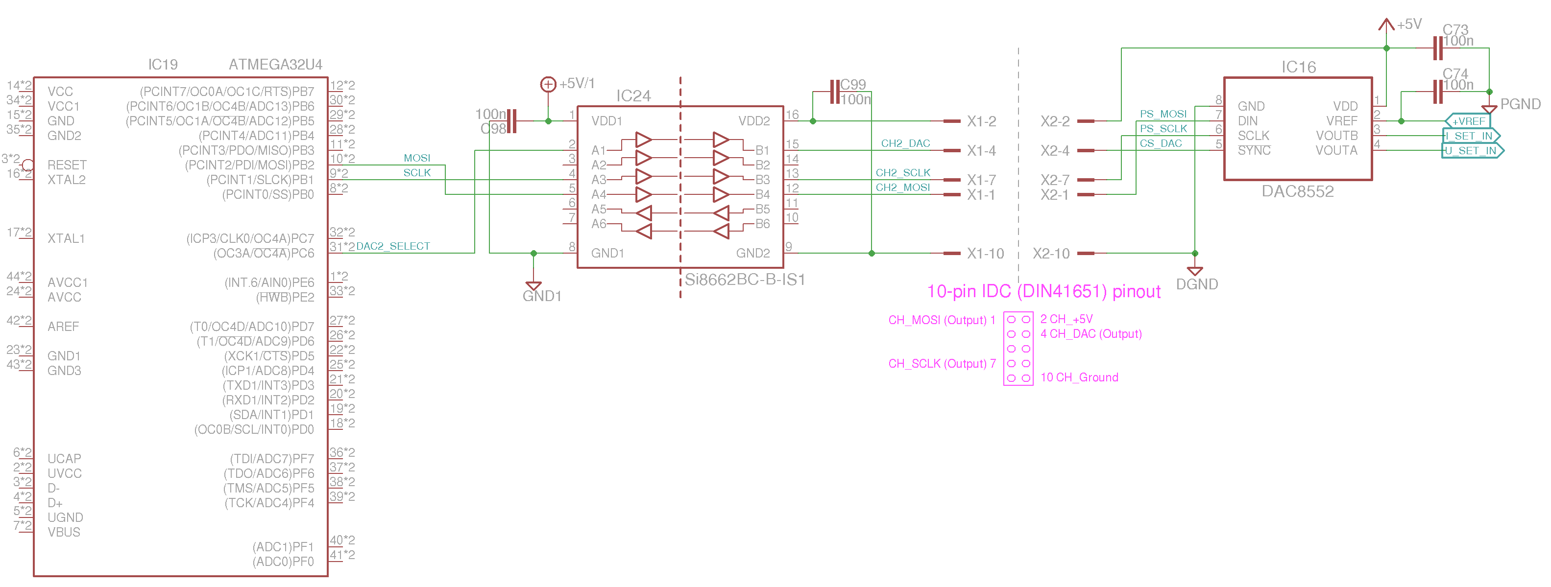
Schematic derived from much complex one is shown below:
Results WITHOUT isolator:

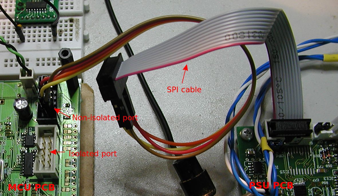
Connection between MCU and PSU PCB:
Here is what I got when isolator is added between MCU and DAC:

I tested it using isolator on MCU PCB ...
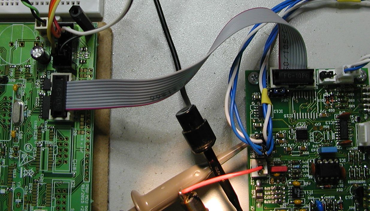
but also to be sure using isolator connected on breadboard to be sure that something is connected wrongly to the MCU PCB:
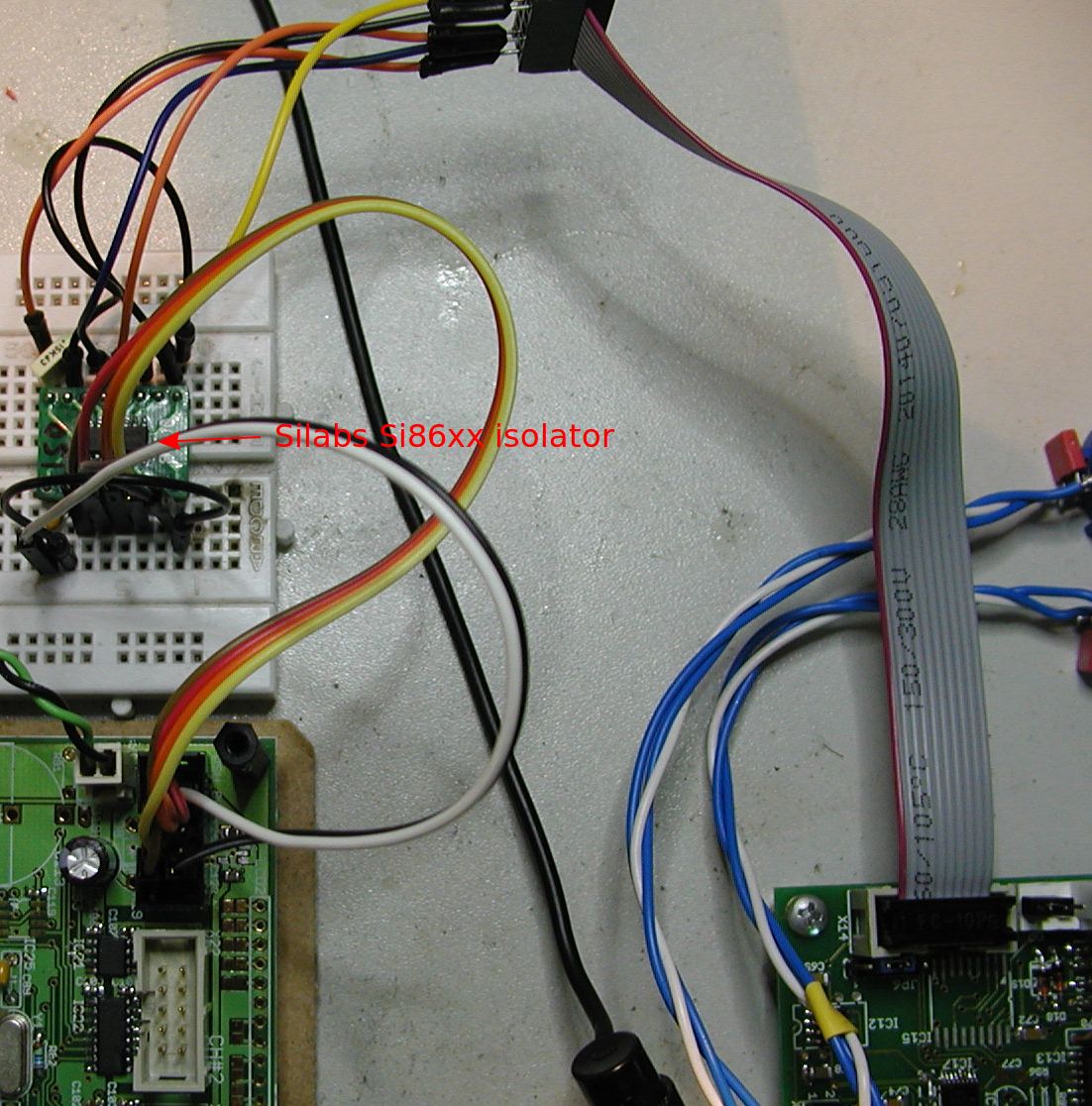
Please note that MCU PCB has two 10-pin IDC connector: black one is a non-isolated SPI, and grey is isolated SPI where "remote" part of the isolator device is supplied from external source (PSU PCB). Intentionally I used the same ribbon cable, and cable length doesn't seems that is an issue since everything works correctly without isolator. To be completely on safe side I tried to slow down SPI clock as much as possible even down to 125kHz (divide by 128 from default 4MHz or divide by 4). Nothing helps in case of isolator - I'm continuously receiving random values on the output instead of fixed two. I also tested the following "hybrid" connection where MOSI and chip select (ADC2_SELECT) goes thru isolator and SCLK is connected directly while MCU ground IS NOT connected to "remote" PSU ground. To my surprise that combination works but I cannot explain why! Also checking signal from the both side of isolator don't shows anything suspicious: signal duration on the "remote" side is slightly shorter since isolator has built-in Schmitt trigger logic.
I ran out of ideas what to test next so if someone has any suggestion please let me know.
EDIT 2015-06-08: I'm adding below two screenshots side by side where on the left is DAC out when SPI is connected directly. It seems that setup of new value is in sync but for some reason value is "shifted" up or down in case of lower value (0x20).

When change is from 0x70 to 0x80 I got the following:

EDIT 2015-06-09: Please find below more measurements as suggested by Tom L. Everything is performed on the breadboard, same wires and flat cable is used as in initially presented results. Grounds on both side of the isolator are tied together, "remote" (or Side B) is supplied from PSU PCB, host (or Side A) from Arduino Leonardo. First I tired using mentioned wiring direct SPI connection and it works as expected. In first step SCLK and MOSI stays directly connected CS (ADC2_SELECT) goes over isolator. All unused isolator pins are grounded. DAC works as you can see on the following two screenshots (S1 is host side, S2 is remote side on the isolator device, DAC signal is analog output on DAC8552 pin 4 (VOUTA):


Same thing when MOSI goes thru isolator and SCLK and CS stayed directly connected:


And now we comes to problem that persist and I cannot figure out what is going on: when SCLK goes thru isolator communication stops regardless of the fact that signal looks fine on both side of the isolator. Please note that on DAC trace there is no more changes. That is one of two possible scenario. Another one is already described (random values are presented on DAC output).


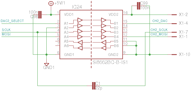
I'm adding one additional scenario when SCLK is connected to host side via capacitor. In that case DAC starts to behave regularly even when grounds are not tied together. Pleas find below schematic and result:
