2
\$\begingroup\$

So far, I was able to get two outputs at the correct resolution (35 kHz-75 kHz at a resolution no worse than 0.7 kHz) using the code below. I'm wondering, now, how I can get a phase shift between the two PWM outputs (which both use the 16-bit Timer1 and ICR1).

I tried writing the line TCNT1 += 1/freq/4; in between the last and second to last lines of code (OCR1A=... and OCR1B =...), but this did nothing.

//set port B to output 
DDRB |= 0xFF; 

// wgm mode 1110 (fast pwm w/ TOP = ICR1
TCCR1A |= 1<<WGM11; 
TCCR1B |= 1<<WGM12 | 1<<WGM13; 

//set OC1/A and OC1B on compare match w/ ICR1 , clear them at bottom
TCCR1A |= 1<<COM1A1 | 1<<COM1A0; 
TCCR1A |= 1<<COM1B1 | 1<<COM1B0; 

//pre-scaler = 1
TCCR1B |= 1<<CS10; 

ICR1 = 16000000/freq; // input compare value = (clock freq) / (desired freq)

// 50% duty cycle on OCR1A/B
OCR1A  = ICR1/2;
//TCNT1 += 1/freq/4; //this line did not do anything
OCR1B = ICR1/2;
\$\endgroup\$
3
  • \$\begingroup\$ Do you just want both wave forms to always be 50% duty cycle, and you can adjust the frequency and the phase shift? \$\endgroup\$
    – bigjosh
    Commented Jun 10, 2015 at 0:39
  • \$\begingroup\$ I'm simulating the output of a quadrature encoder. So I need to be able to vary the frequency, but the duty cycle will always be 50% and the phase shift will always be plus or minus 90 degrees, though the delay for this will change along with the frequency. See Answer 2 below for my current status. \$\endgroup\$ Commented Jun 10, 2015 at 2:01
  • \$\begingroup\$ The TCNT is a counter that is being updated by the hardware, so any changes you make to it just reset it value at the moment you change it. CHeck out my answer below for a way to get the two outputs to trigger at different times in the TCNT cycle. \$\endgroup\$
    – bigjosh
    Commented Jun 10, 2015 at 4:10

3 Answers 3

3
\$\begingroup\$

If your application only requires waveforms with 50% duty cycle, then you can use the toggle compare output modes to generate a pair of signals with adjustable phase shift between them.

The toggle modes will toggle their respective output each time there is a compare match, so by adjusting the 2 output compare registers relative to each other, you change the phase relationship. You adjust the frequency of both signals together by changing the TOP for the counter.

Make sense?

Here is some demo code for an Arduino Uno. It will output 50KHz square waves on Arduino Pins 9 & 10, and cycle though phase shifts of 0, 90, and 180 degrees - pausing on each for one second.

// This code demonstrates how to generate two output signals
// with variable phase shift between them using an AVR Timer 

// The output shows up on Arduino pin 9, 10

// More AVR Timer Tricks at http://josh.com

void setup() {
  pinMode( 9 , OUTPUT );    // Arduino Pin  9 = OCR1A
  pinMode( 10 , OUTPUT );   // Arduino Pin 10 = OCR1B

  // Both outputs in toggle mode  
  TCCR1A = _BV( COM1A0 ) |_BV( COM1B0 );


  // CTC Waveform Generation Mode
  // TOP=ICR1  
  // Note clock is left off for now

  TCCR1B = _BV( WGM13) | _BV( WGM12);

  OCR1A = 0;    // First output is the base, it always toggles at 0


}

// prescaler of 1 will get us 8MHz - 488Hz
// User a higher prescaler for lower freqncies

#define PRESCALER 1
#define PRESCALER_BITS 0x01

#define CLK 16000000UL    // Default clock speed is 16MHz on Arduino Uno

// Output phase shifted wave forms on Arduino Pins 9 & 10
// freq = freqnecy in Hertz (  122 < freq <8000000 )
// shift = phase shift in degrees ( 0 <= shift < 180 )

// Do do shifts 180-360 degrees, you could invert the OCR1B by doing an extra toggle using FOC

/// Note phase shifts will be rounded down to the next neared possible value so the higher the frequency, the less phase shift resolution you get. At 8Mhz, you can only have 0 or 180 degrees because there are only 2 clock ticks per cycle.  

int setWaveforms( unsigned long freq , int shift ) {

  // This assumes prescaler = 1. For lower freqnecies, use a larger prescaler.

  unsigned long clocks_per_toggle = (CLK / freq) / 2;    // /2 becuase it takes 2 toggles to make a full wave

  ICR1 = clocks_per_toggle;

  unsigned long offset_clocks = (clocks_per_toggle * shift) / 180UL; // Do mult first to save precision

  OCR1B= offset_clocks;

  // Turn on timer now if is was not already on
  // Clock source = clkio/1 (no prescaling)
  // Note: you could use a prescaller here for lower freqnencies
  TCCR1B |= _BV( CS10 ); 

}

// Demo by cycling through some phase shifts at 50Khz  

void loop() {

  setWaveforms( 50000 , 0 );

  delay(1000); 

  setWaveforms( 50000 , 90 );

  delay(1000); 

  setWaveforms( 50000 , 180 );

  delay(1000); 


}

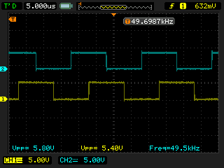
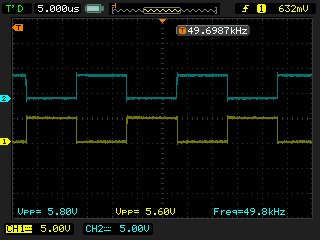
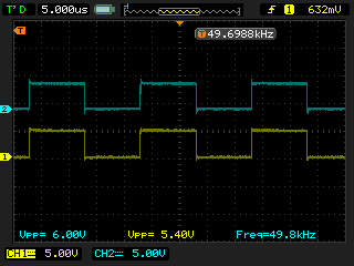
Here are some scope traces of the 0, 90, and 180 degree shifts respectively...
0 degree shift

90 degree shift

180 degree shift

\$\endgroup\$
11
  • \$\begingroup\$ Wow, thank you so much! This works well except for one thing -- sometimes the wave that should be leading by 90 degrees actually ends up lagging. I can see it flip on the oscilloscope, and I'm not sure why it happens -- it seems random, and sometimes it actually flips back upright and corrects itself. Might it be skipping clock counts on the compare register? Thanks again! \$\endgroup\$ Commented Jun 10, 2015 at 19:56
  • \$\begingroup\$ I assume you see the flip when you are actively changing the parameters? If so, this is likely a timing issue. Because there is no double buffering of the OCR registers in CTC modes, you have to be very careful about when you make updates. It is possible for you to miss a compare, which would mean missing a toggle, which would make the wave upside down until the next time you miss a toggle. \$\endgroup\$
    – bigjosh
    Commented Jun 10, 2015 at 20:04
  • \$\begingroup\$ The best way to avoid this problem depends a lot on your specific application requirements. One way is to restart the timer from scratch each time you change the phase or frequency. This is super simple and always results in correct waveform generation while running, but it causes glitches at the moment you do the switch. Would something like this work for your application? \$\endgroup\$
    – bigjosh
    Commented Jun 10, 2015 at 20:06
  • \$\begingroup\$ Should I start a new question on this subject? I think the code would better illustrate it. But basically what I'm doing is having an input square wave determine the frequency, and the outputs have to match that frequency. I'm using pulseIn() to determine the period of the input, converting it to frequency, and then feeding it to the setWaveforms function. At high frequencies, pulseIn is kind of shoddy with resolution (a possible solution to my problem would be improving this, I think), so I smooth it out by averaging 100 samples at a time. \$\endgroup\$ Commented Jun 10, 2015 at 20:47
  • \$\begingroup\$ Then I feed this into the setWaveforms function continuously. I suppose what I could do is wait for it to iterate a couple hundred times, and only then turn the waveform -- so it's not starting at 8Mhz and going down to where it needs to be each time... I'll give that a shot actually. Update: This actually worked like a charm, thanks again! \$\endgroup\$ Commented Jun 10, 2015 at 20:49
1
\$\begingroup\$

You can't have a phase shift between multiple signals in PWM mode using a single timer. Each shift will have to be on a separate timer, and you will need to offset each counter the appropriate amount.

\$\endgroup\$
14
  • \$\begingroup\$ There's no way to add a delay in the initialization or anything like that? The problem is that the other 2 timers don't have an input capture register, so they don't let me adjust the frequency as easily -- nor do they have as precise of a resolution. \$\endgroup\$ Commented Jun 9, 2015 at 15:27
  • \$\begingroup\$ If not, should I be using a different microcontroller? Maybe you could suggest something... I looked into the dsPIC30F4011/4012 and the motor control PWM seems like it'd do the trick (namely, variable frequency two-output PWM with 90 degree phase shift), but I'm not sure if that's overkill. Maybe an AtTiny? \$\endgroup\$ Commented Jun 9, 2015 at 15:42
  • \$\begingroup\$ If you read the relevant parts of the datasheet about how the timer works, it should be obvious why you can't do this - the timer either sets or clears the relevant pins when the timer overflows, so all outputs on the timer will have that edge in common. Which AVR is this? Most of them have >1 timer that supports adjustable TOP values. \$\endgroup\$ Commented Jun 9, 2015 at 15:49
  • \$\begingroup\$ Sorry, should've included that: ATMEL328P \$\endgroup\$ Commented Jun 9, 2015 at 16:23
  • \$\begingroup\$ All three timers on the ATMega328P can have TOP values configured by writing to their respective OCRxA registers. \$\endgroup\$ Commented Jun 9, 2015 at 16:43
0
\$\begingroup\$

This code is still not entirely correct -- the phase shift gets more and more messed up as frequency decreases, and I'll also have to add in a pre-scaler for anything below 62 kHz -- but at 75 kHz, it works!

I guess now the question is not "How do I get a delay between the two PWMs?" but rather, "How do I get the delay to scale with the frequency?"

int main ()   
{
  //************************* Timer 0 *********************************

    // wgm mode 111 (fast pwm w/ TOP = OCRA)
TCCR0A |=  1<<WGM00 | 1<<WGM01; 
TCCR0B |= 1<<WGM02; 

    //set COM0x1 (non-inverting mode)
    TCCR0A |=  1<<COM0A1 ; 
    TCCR0A |=  1<<COM0B1 ; 

    //pre-scaler = 1
    TCCR0B |=  1<<CS00; 


    // arbitrary frequency
OCR0A  = 220; //counts until TCNT = OCR0A then resets
    OCR0B = OCR0A/2; //on until TCNT = OCR0B then off

     // turn on pin D5
    DDRD |= 1<<PIND5;

   TCNT2 += OCR0A/4 ; //add a 90 degree delay to TCNT2... or something like that

//**************************** Timer 2 ****************************************
    // wgm mode 111 (phase-corrected pwm w/ TOP = OCRA)
TCCR2A |=  1<<WGM20 | 1<<WGM21; 
TCCR2B |= 1<<WGM22; 

    //set COM0x1 (non-inverting mode)
    TCCR2A |=  1<<COM2A1 ; 
    TCCR2A |=  1<<COM2B1 ; 

    //pre-scaler = 1
    TCCR2B |=  1<<CS20; 


    // same frequency as above pwm on timer 0
OCR2A  = OCR0A; 
    OCR2B = OCR2A/2;


     // turn on pin D3
    DDRD |= 1<<PIND3;
    }
\$\endgroup\$
2
  • \$\begingroup\$ Did you try resetting the delay each time you set the frequency? \$\endgroup\$ Commented Jun 9, 2015 at 20:43
  • \$\begingroup\$ Each time I changed the frequency (OCR0A = 220) I had to re-upload the file onto the Arduino, so if that's what you mean, then yeah. \$\endgroup\$ Commented Jun 10, 2015 at 1:58

Not the answer you're looking for? Browse other questions tagged or ask your own question.