2
\$\begingroup\$

I've got a bunch of these integrated H-bridge & driver IC's in my stock and wish to use them in an upcoming design:

http://www.toshiba.com/taec/components2/Datasheet_Sync/201006/DST_TB6593FNG-TDE_EN_27195.pdf

However, these IC's can only drive 3.2A. I would like to augment the current handling capability of these existing IC's to be able to drive about 6A through a solenoid. I do not want to buy new stock of beefier H-bridge/driver IC's, if possible.

The solenoid itself has parameters of R=2ohms, L=1mH

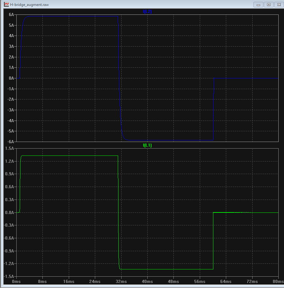
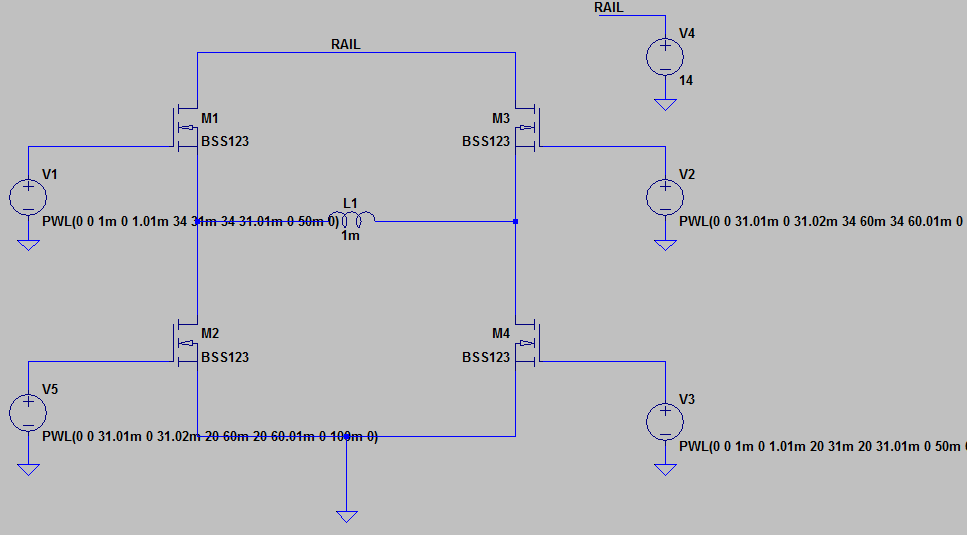
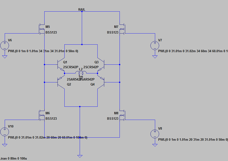
I simulated a proof-of-concept, barebones circuit to augment drive capability consisting of two push-pull pairs that are driven by the H-bridge outputs, and those BJT's then drive the bulk of current through the solenoid. The H-bridge itself is generic; I simply put it together in LTSpice with some high Ron MOSFETs to simulate the current limitation of the IC, for which a macro model does not exist. Results are illustrated below:
enter image description here

enter image description here

enter image description here

Questions about this approach:

(1) Is this a safe way to augment the capability of this IC, or other similar IC's? (2) What can I add to augmented circuit above to simulate more accurate real-world behavior? (3) Is this approach ever used in industry? Or is there a better method?
(4) Are there any pitfalls or "gotchas" with the augmented circuit above?

\$\endgroup\$
4
  • 4
    \$\begingroup\$ You're basically building an H-Bridge of your own - in which case, why use the IC at all? A simple alternative would be to parallel two of the existing ICs, which will give you a maximum current somewhere between the original rating and twice that. \$\endgroup\$ Commented Jul 14, 2015 at 15:46
  • \$\begingroup\$ I'm using the IC because: (1) The timing & control circuitry is already integrated (2) the charge pump circuitry is already integrated. These are both sub blocks that I do not have any interest in replicating. Paralleling these IC's might indeed work; however, paralleling two of these IC's is more expensive than just using a single IC and 4 cheap BJT's \$\endgroup\$
    – smoothVTer
    Commented Jul 14, 2015 at 17:03
  • \$\begingroup\$ Have you considered the loss in the BJT's? Also, do you actually need to be able to drive this coil bidirectionally? \$\endgroup\$ Commented Jul 14, 2015 at 17:10
  • \$\begingroup\$ I have considered the losses in the BJT's, yes. For my purposes they are acceptable since the solenoid is used sporadic fashion. The coil does indeed need to be driven bi-directionally, as it is a latching solenoid; it latches when we have current in one direction and unlatches when we have current in the opposite direction. \$\endgroup\$
    – smoothVTer
    Commented Jul 14, 2015 at 17:34

1 Answer 1

1
\$\begingroup\$

What @Chris is saying is that your BJTs will get very warm with 6A flowing thru them because they are configured as push-pull emitter followers and, because of this, will inevitably drop about a volt across the conducting transistors.

Now, figure out how much that electricity costs to throw away and decide which is the cheaper option - the ones you have in your box (presumably paid for) or the new transistors dissipating about 12 watts all the time the solenoid is being driven.

Having said all of that the existing chips have a total (upper and lower) on resistance of 0.35 ohms (see page 5 of the data sheet) and, 2 of them in parallel at 6A will waste about 6.3 watts total. Get a better device is my advice and save the world.

\$\endgroup\$

Your Answer

By clicking “Post Your Answer”, you agree to our terms of service and acknowledge you have read our privacy policy.

Not the answer you're looking for? Browse other questions tagged or ask your own question.