1
\$\begingroup\$

I have an RF power amplifier (PA) for a transceiver module I'm designing. My transceiver is capable of outputting +14 dBm at the 915 MHz ISM band and the RF PA will be used to further amplify the output to +30 dBm. When not requiring the 1W output power, I would like to use the shutdown mode of the PA.

Would it be possible to have a SPST RF switch with one end connected on the RF input to the PA and the other to its output to bypass the PA when shutdown? Will this affect the RF too much (if so, how)?

The other option would be to have two SPDT RF switches to create separate RF paths - except this adds an extra 0.5 dB insertion loss.

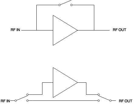
RF Switches

\$\endgroup\$

1 Answer 1

1
\$\begingroup\$

If you want to bypass the PA, you'll need to have a separate RF path. If you just put the SPST in parallel with the PA, you'll be making a very crude splitter with one path that has gain. This will pretty much kill any isolation you have and you'll basically make a feedback loop.

If you want to bypass the PA, you'll need to do something like you suggested with the SPDT low power path. You can probably find a PA with built in bypassing, honestly.

Now, if you have the PA in shutdown mode such that there is no gain, then the feedback and oscillation is not a problem. However, you'll still have a rather large impedance mismatch if you don't design your circuit correctly. The chip you've linked has a 1.5 VSWR when in shutdown, which means that you'll actually split a lot of your power with the SPST approach. You'll need to create that bypass path.

\$\endgroup\$
6
  • \$\begingroup\$ This makes sense, I appreciate the explanation. I was going to use the MAX2235 but I do not think bypassing is possible. It is hard to find PA's that go up to +30 dBm. \$\endgroup\$ Commented Jul 15, 2015 at 4:35
  • \$\begingroup\$ Yes, however you could use multiple RF amplifiers and combine them. You would need to fully understand the FCC implications. I've edited my answer above. \$\endgroup\$
    – scld
    Commented Jul 15, 2015 at 4:37
  • \$\begingroup\$ The two components are the MAX2235 and SKY13453-385LF. The PA says "Standby mode input VSWR Change" is 1.5:1, but if I have the SPDT switches bypassing the PA completely, why do I need a good input/output match to the PA? \$\endgroup\$ Commented Jul 15, 2015 at 4:47
  • \$\begingroup\$ Because you're physically bypassing, you don't need a good match in shutdown mode. There are other applications where a good match in shutdown mode is preferred but outside the scope of this question. \$\endgroup\$
    – scld
    Commented Jul 15, 2015 at 15:40
  • \$\begingroup\$ Understand now, thanks. I thought you meant a good impedance match for the physically bypassed approach - hence my confusion. How did you acquire your RF experience, if you don't mind my asking? \$\endgroup\$ Commented Jul 16, 2015 at 0:42

Your Answer

By clicking “Post Your Answer”, you agree to our terms of service and acknowledge you have read our privacy policy.

Not the answer you're looking for? Browse other questions tagged or ask your own question.