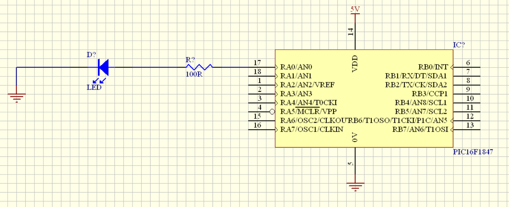
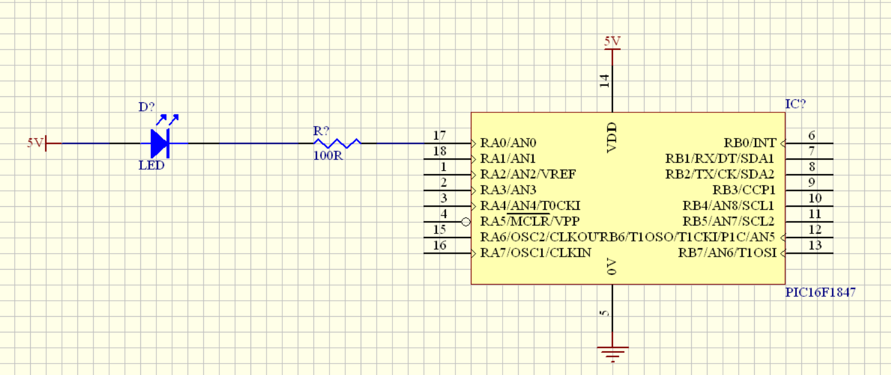
It is possible that the first circuit does not work depending on the internals of the MCU.
Usually, a pin can source or sink a current. In this case, it does not matter, which circuit you choose, only the logic will be inverted.
This sketch may give you an idea how this works inside the MCU:

simulate this circuit – Schematic created using CircuitLab
Depending on the state of the output, one of the LEDs will always be on.
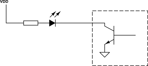
But a pin could also be an open-collector output, which can be sketched like this:

simulate this circuit
An open-collector can only sink current, so the LED circuit works only in the direction shown in my sketch.
I'm familiar with Microchips PIC18F2550/2455/4550/44555 family, which have the RA4-"feature". While all outputs are CMOS outputs, RA4 is an open drain output and I guess everybody using this MCUs once forgot that.
However, an open collector/drain output also has the advantage of switching voltages higher than the MCU supply voltage. The mentioned MCU can switch up to 8V on RA4, even if itself is only powered by 3.3V.
For your PIC16F1847, check the tables on pages 13-16 of the datasheet. All I/Os are of type "CMOS", but you'll find pins which will be "OD" in I²C mode. But this is by general I²C design.
So, it does not matter which direction you choose for an LED at your MCU.


