I'm trying to drive an LED with a square wave / pulses and look at the output with a photodiode / transimpedance amp detector. The starting frequency is about 1 KHz but I will eventually go up to about 100 Khz. The problem I'm running into is non-square LED output waveforms being sensed by the detector. In the scope capture, channel 1 is the driving waveform, channel 4 is the signal at the LED and channel 3 is the detector output. My first thought was to try a different LED driver circuit, specifically a shunt driver configuration. I read online that adding some RC components could speed it up (increase the slew rate). I found on another site something similar albeit a digital driver that uses dual inverters as drivers. Could someone explain to me what these RC networks are doing (specifically) and how to determine the appropriate values for them? Thanks in advance.
-
\$\begingroup\$ I would say that it is just taking time to LED to go from the OFF state to the full ON state. As well as for the photodetector to consume it. If you want to get a square wave out of photodetector, just add a comparator stage with some threshold. \$\endgroup\$– Eugene Sh.Commented Aug 18, 2015 at 21:24
-
\$\begingroup\$ Are you using a commercial photodetector with a known rise/fall time? \$\endgroup\$– Spehro 'speff' PefhanyCommented Aug 18, 2015 at 22:00
-
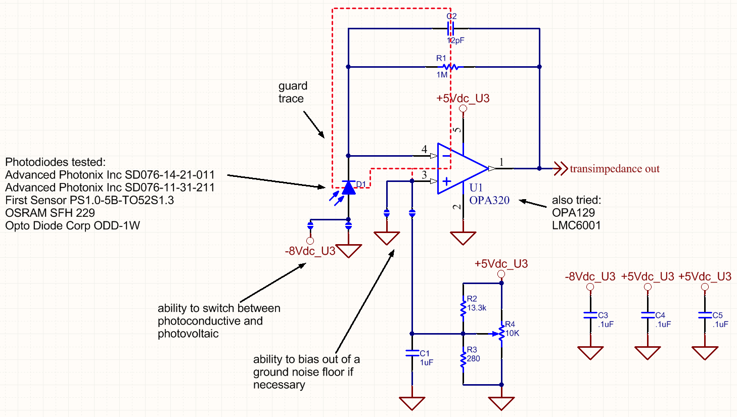
\$\begingroup\$ Your problem is almost certainly your detector/TIA. Please provide a part number for the PD, and a schematic for the amplifier. \$\endgroup\$– WhatRoughBeastCommented Aug 18, 2015 at 23:42
-
1\$\begingroup\$ I'll add that if it is a "white" LED, they often employ phosphorescence (a "white stuff" similar to what's inside mercury vapor lamps or CCFL's) to convert the blue-ish colors of the actual LED die into the white color we perceive. In any case, that takes time. How much time, I am not sure, but I bet it slows down the light output somewhat. \$\endgroup\$– rdtscCommented Aug 19, 2015 at 1:55
-
\$\begingroup\$ If you require really fast pulses, look into a low-power solid-state laser diode. \$\endgroup\$– rdtscCommented Aug 19, 2015 at 1:56
1 Answer
The capacitor in the RC circuit effectively bypasses the resistor for a short time to provide a "gulp" of current for the device. The setup is reminiscent of a boot strap. Lets take the faster shunt driver as an example. To keep D3 off Q3 is on and diverting current away from D3. This sets up a voltage drop across R7 which is stored in C2. When Q3 turns off the point of C2 which was sitting at ground gets lifted to 5V causing the charge stored in it to push into D3. This push makes available a short burst of current helping to turn on D3 faster.
-
\$\begingroup\$ Exactly the kind of thing I was looking for. I assume the same holds true for C1 in providing current for the base of Q3? How are the values of these RC circuits determined relative to operating frequency / desired slew rate? Also, wouldn't these "gulps" of current risk damaging the transistor base and LED? How do you take that into consideration when picking values? Moving on to the fast optical pulse driver, I see the same thing in C3/R10, but what is the purpose of the R12 pulldown and R9/C4 series RC circuits? \$\endgroup\$ Commented Aug 20, 2015 at 15:18


