1
\$\begingroup\$

Well I am currently working on building a battery gauge via LED. My target is a red LED to blink if batteries are going to die and a green LED to blink if the batteries are fine.

Researching on that topic different questions already have been considered and mostly referred to a link such as http://batteryuniversity.com/learn/article/how_to_measure_state_of_charge. Knowing the limitations I was planning to make use of the Voltage Method. The batteries I was planning to use were NiMh enveloop pro batteries (AA). Considering the tests on the battery (I couldn’t find the datasheet) the http://www.stefanv.com/electronics/sanyo_eneloop.html I found out that the battery mostly crosses below 1,1V before dying. Therefore I was planning to use 1.1V per Battery as a threshold or indication that the battery will die. To apply the voltage method beneficially, using the internal 1.1V reference voltage of the Adafruit Trinket Pro (according to the datasheet of atmega 328p, which can be found in the Trinket) has to be measured against the input voltage(as described :http://wp.josh.com/2014/11/06/battery-fuel-guage-with-zero-parts-and-zero-pins-on-avr/).

However my issue is that I make use of an Adafruit Trinket Pro 3V and a Servo having one source of battery (4XAA NiMh). 4.8V are provided to the Servo. A buck converter is attached between the battery and the Trinket in order to provide it with its required 3.3V.

Generally using the Voltage method for a battery gauge the ADC Pin is compared to Vcc Pin as described above. However in my case the microcontroller will always receive 3.3V. Any voltage drop of the battery will only affect the servo since the buck converter will make sure to provide the microcontroller with sufficient voltage. Therefore using the voltage method I do not know how I may identify any voltage drop on the 4.8V battery source because the voltage drop will have no effect on the Adafruit Trinket.

Given these circumstances is there a way to make a battery gauge making use of the voltage method or any other beneficial way? I am aware that the difference in VBAT and VCC might complicate the issue..

Information Adafruit trinket: https://learn.adafruit.com/introducing-pro-trinket/overview Datasheet atmega 328p: http://www.adafruit.com/datasheets/ATMEGA328P.pdf

\$\endgroup\$
2
  • \$\begingroup\$ Have you considered using a bare MCU so that you won't need any regulator at all? \$\endgroup\$ Commented Aug 26, 2015 at 20:54
  • \$\begingroup\$ @IgnacioVazquez-Abrams Do you mean to use a MCU and power it with 4.8 V as well? ....well I am using the Trinket Pro 3V in order to reduce power consumptioN whilst still having an UART and being able to connect to a BLE module which also requires 3V \$\endgroup\$
    – Sathees
    Commented Aug 26, 2015 at 21:08

3 Answers 3

1
\$\begingroup\$

Since you want to use a regulator, you can't assume Vbat=Vcc. So you need to use an external pin to measure battery voltage.

The most simple method I can think of is a voltage divider tied to an ADC pin (if you want full voltage level) or an analog comparator pin (if you only need 1.1v threshold; you can use the internal reference as the other input to the internal comparator)

However you need to use resistor values high enough for an acceptable current draw, and low enough for adc input impedance and noise. A cap across input pin may help with noise and for storing enough charge for the adc s/h capacitor noise.

And if you need very low average power draw, you can tie the ground side of the resistor divider to a digital pin or (better) tie the upper side to a p-mosfet whose gate is controlled by a digital pin. This way you can enable the divider only while you're actually measuring it.

In any case I don't think you need an external comparator unless you need advanced features (super low offset voltage, for example) the AVR peripherals don't provide.

\$\endgroup\$
0
\$\begingroup\$

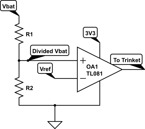
I believe you could use a comparator with a voltage reference to output a 3.3V signal as to whether the battery is getting low or now. Basically you could use a voltage divider on your Vbat to divide it down to 1/4th your Vbat, so around 1.2V. Since the voltage when its low dips below 1.1V, you can use a 1.1V voltage reference. Connect them both to a comparator.

schematic

simulate this circuit – Schematic created using CircuitLab

I just threw this schematic together, so the orientation of the comparator may be wrong and I didn't even attempt the resistor values.

But this is the general idea.

\$\endgroup\$
0
\$\begingroup\$

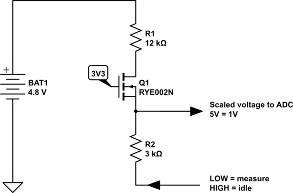
To measure a battery voltage, you need a resistor divider and a transistor.

This design uses two microcontroller pins, an ADC input and a digital output.

To make a measurement, set the digital pin to a low output, then read the ADC.

After the measurement digital output high to turn off the transistor and avoid wasting current.

RYE002N is chosen for its low threshold voltage. If the threshold voltage is too high, accuracy is compromised at high battery voltages. This may not be important for this application.

With these values, a voltage of 4.4V will apply 0.88 V to the ADC.

schematic

simulate this circuit – Schematic created using CircuitLab

\$\endgroup\$

Your Answer

By clicking “Post Your Answer”, you agree to our terms of service and acknowledge you have read our privacy policy.

Not the answer you're looking for? Browse other questions tagged or ask your own question.