5
\$\begingroup\$

I am trying to get +/- 12V and +/- 5V voltage in my board. I am getting lot of noise on the primary side itself as well it is carrying to the secondary side. I am driving the MOSFET with 100KHz PWM signal from microcontroller. I am thinking the source of noise is MOSFET switching. The schematic is as shown below Schematic
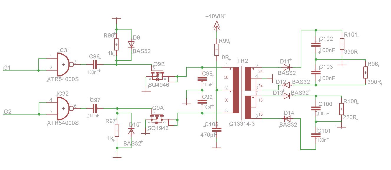
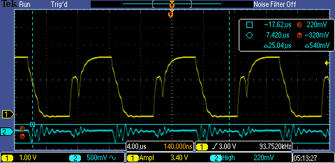
I have 3.3V PWM signal from controller but at the MOSFET gate I have a voltage -0.8 to 2.5V, thinking which is not sufficient to open completely. If I remove the capacitor C96 and added 50ohm resistor then I can see 0 to 3.3V signal at gate. still I have noise on primary side as well I increased capacitor C98, C99 to 1nF.

Noise is appearing on ground as well and same noise is effecting PWM signal at microcontroller. I am out of ideas on how to remove that noise. Any suggestions can be appreciated.

I tried to add some oscilloscope shots since I don't have reputation in this site so I can't update.

switching is like one MOSFET is switched OFF while another is ON, both MOSFETs never ON at a time.

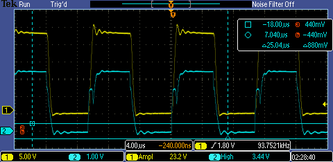
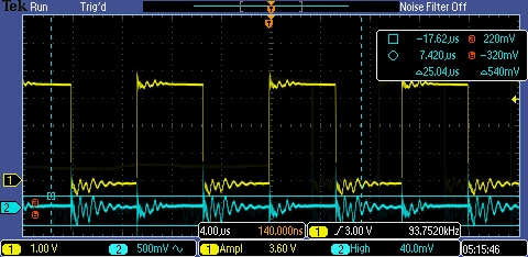
Some oscilloscope shots

Yellow signal at MOSFET gate and blue is ground

ellow signal is PWM at microcontroller pin and blue is ground on MOSFET

I have added a 250 ohm resistance between MOSFET gate and IC31 NAND gate by removing capacitor C96, C97 and diode resistance network. it means i gave direct PWM signal after NAND gate. I got less noise but still noise is there, below are the scope shots. Noise and primery side signal Gate signal and primary side signal
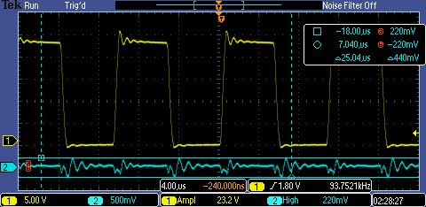
I have a noise on signal as well on ground so can it be some curret floating on the board which is causing noise?

\$\endgroup\$
8
  • 2
    \$\begingroup\$ Why are C96 and C97 there ? I would just drive the gates directly from IC31 and IC32. \$\endgroup\$ Commented Oct 1, 2015 at 14:35
  • 3
    \$\begingroup\$ How do you avoid shoot thru (both mosfets turning on for a few nano seconds)? \$\endgroup\$
    – Andy aka
    Commented Oct 1, 2015 at 14:35
  • 2
    \$\begingroup\$ Regarding noise: for switched converters noise and ripple is a fact of life, you cannot avoid it. Filtering helps, I see 100nF caps at the output, that is a very small value. I would use 10 uF in parallel with each 100 nF. Maybe a coil/choke is needed in series with the 4 diodes. \$\endgroup\$ Commented Oct 1, 2015 at 14:38
  • \$\begingroup\$ You are only half wave rectifying each of the transformer output voltages. additional diodes will reduce the ripple on all outputs significantly. + bigger output capacitors as FakeMoustache says. \$\endgroup\$
    – Icy
    Commented Oct 1, 2015 at 15:07
  • \$\begingroup\$ You can link to external images though. Upload (scope shots etc.) to imgur.com and link to them. \$\endgroup\$ Commented Oct 1, 2015 at 22:51

2 Answers 2

2
\$\begingroup\$

1) Do not turn on one mosfet while the other isn't completely off. Not only the 250ohm resistor: add some dead time (time when no one of the mosfets is on) in your firmware, if you can;

2) Adding this dead time perhaps will obligate you to increase the output capacitors. And I agree with FakeMoustache that you need some bigger values of output capacitors than 100nF;

3) Very small value inductors, (again, as commented by FakeMoustache) more than once made miracles against my SMPSs output noises. You can begin with 1uH. If you want to test very high values of inductors, pay attention to the self resonant frequency (SRF) of it: I like to use at least 10 times the noise frequency;

4) Tip (if you aren't already doing it): be sure that you are measuring the noise very close to the output (and without the ground clip of the oscilloscope), in order to be closer of its true value and make good comparisons while testing;

5) Perhaps it won't change the output noise (but in the overall circuit), but I can't avoid my will to write you to add one inductor in the place of R99 and close to it one 100nF paralleled to a 10nF (attached to +10Vin and ground). This may attenuate the conducted noise to the +10Vin that you will experience.

Best regards

\$\endgroup\$
0
\$\begingroup\$

Some ways to reduce noise in a SMPS:

-Select lower switching frequencies, but this will increase the heat generated on the mosfets and reduce efficiency.

-Select the right capacitor (low ESR and low inductance) to put in parallel with the mosfest to reduce ringing (search for "ringing" in switched mode power supplies if you want to know more).

Some of the noise you get in you scope may be getting there trough emission. You can put your probe in a loop and get near the circuit, just to check... But keep in mid that there will always be some noise.

\$\endgroup\$

Your Answer

By clicking “Post Your Answer”, you agree to our terms of service and acknowledge you have read our privacy policy.

Not the answer you're looking for? Browse other questions tagged or ask your own question.