6
\$\begingroup\$

I have The Executioner bug zapper:

enter image description here

Although it uses 2 AA 1.5v batteries, it also has voltage multiplier like Cockcroft–Walton generator i guess and would like to know if it is safe and would make sense to use multimeter for measuring zapper's voltage output and preferrably resistance as well.

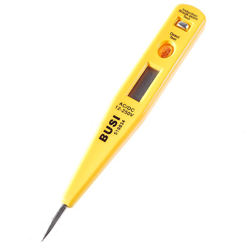
UPDATE: Can i also test voltage output with voltage tester like this? Will it be better than multimeter in this case?

enter image description here

\$\endgroup\$
5
  • \$\begingroup\$ I have a different one but it's the same basic item, and it has a marking "2300V Volts" [sic] on the handle. Very unlikely to be exactly that, but that's the rough magnitude of the voltage involved. \$\endgroup\$
    – JustJeff
    Commented Sep 16, 2011 at 22:03
  • \$\begingroup\$ So can i do it with this voltage tester? \$\endgroup\$
    – Boris_yo
    Commented Sep 17, 2011 at 15:03
  • \$\begingroup\$ the zapper puts out a couple of thousand volts. the tester in the picture clearly says 250V. that tester is intended for mains voltages, not the 10x greater output of the bug zapper. \$\endgroup\$
    – JustJeff
    Commented Sep 17, 2011 at 20:22
  • \$\begingroup\$ JustJeff, how is it possible to turn 1.5v batteries' voltage into thousands of voltages? Zapper has voltage multiplier but how is it possible to multiply so many times? \$\endgroup\$
    – Boris_yo
    Commented Sep 18, 2011 at 13:41
  • \$\begingroup\$ With a pair of 1.5s in series you get 3V. That's enough to run an oscillator to create alternating current, which goes into a transformer, which runs it up to probably at least 500 to 1000V. From there, a voltage multiplying rectifier would easily get you peaks of a couple kV, which can be stored up in a capacitor. It's the same kind of thing they use for cold-cathode fluorescent lights. \$\endgroup\$
    – JustJeff
    Commented Sep 18, 2011 at 19:09

2 Answers 2

9
\$\begingroup\$

Interesting question - I would say not with a standard multimeter no.

One problem is (if it's similar to one I have seen) the voltage will be very high (>kV region) and the other is it is probably not stable DC, rather I think it is very short peaks (which will probably confuse even the AC setting on most multimeters) although further research says this is probably not the case. In any case, the amount of charge supplied should be very small so it will probably be quite safe. Having a look at the circuit and running the calculations might be a good idea, as the voltage level (alone) is not the full story, the current matters, and although a capacitor can present a very low impedance, the output cap would need to be large enough to source it for a reasonable length of time. You might get a similar (harmless) shock from a piezo spark module found in e.g. a cheap lighter.

Wiki says:

Most flyswatters conform to electrical safety standards for humans: a limit on the charge stored in the capacitor. A discharge of less than 45 µC is considered safe, even in the unlikely scenario that the current from a flyswatter would be flowing from one arm to the other arm, partly through the heart.1 This means that the capacitor of a 1000 V flyswatter should be less than 45 nF. Due to this precaution for humans the initial shock is usually inadequate to kill flies. a limit on the current after the initial discharge. The maximal continuous current of most flyswatters is less than 5 mA. This current is safe, even when flowing from one arm to the other arm.[2]

To answer the question of voltage measurement:

If pulsed (or significant variation of output levels over small amount of time)

With the multimeter, if it short peaks you would need some way to average the voltage and reduce it to measurable levels - filtering with a capacitor and large restive divider would do this but the capacitors voltage rating (high) and leakage (low) would need to be suitable, plus it may be dangerous depending on the size of the capacitor (see above). You might need many megaohms of resistance in the divider to stop any "loading" of the voltage. The average current in needs to be higher than the current out so the capacitor can charge. I'm not sure if this method would be very easy to achieve satisfactory results with.
EDIT - If you can modify the circuit to stop the automatic discharge of the capacitor (i.e. the circuits output capacitor, not an external one as mentioned above) then measure with high resistance divider (e.g. 50:1, total resistance say, >10 megaohm), that is probably the safest way to try, though you will need to factor your multimeters input impedance into things.

An oscilloscope would be better, as there would be no need for the filtering and the input resistance is very high. You could maybe use a step down transformer to reduce the voltage and the impedance of the signal so loading was less of an issue, or use a HV (e.g. 100:1) probe to measure peaks.

If not pulsed (reasonably stable DC)

If it does not automatically discharge/spark or continually pulse charge the cap (e.g. charges up then holds), then measuring without modification using the divider mentioned should be possible, so would make things easier. I think this may be the case according to the Wiki and other pages (maybe the one I saw worked differently, I seem to remember it clicking/sparking)

\$\endgroup\$
1
  • 1
    \$\begingroup\$ I wrote an answer that basically summarizes part of yours, so I'll dump it here: Go for it, but bump up the input impedance to 10 megohm and divide the voltage down. Using a 10:1 voltage divider with megohm resistors will make the measurement noisy, but keep current down to puny amounts (μA's), allowing the puny high voltage multiplier and cap to maintain its charge and voltage. Check the manual, but your meter probably has 1 megohm input resistance. \$\endgroup\$
    – tyblu
    Commented Jan 24, 2012 at 1:54
5
\$\begingroup\$

I would recommend not doing that, but that's just me.

(1) your meter might not like it, even if it seems it might. The multimeter I have at home (of the $50 persuasion) claims to have a 3000V scale. In the process of trying to diagnose the 'B+' supply in a tube radio one time, I notice that this meter began to act very strangely when trying to show the nominal 750V DC B+ value. The display blinked off and back on erratically, etc. I do still use the 3000V scale, I just don't use the meter for anything much over 500V since then. Better meters will probably work as advertised, but don't expect much if (like me) you tried to cheap out on it.

(2) your hide might not like it. When you start working with high voltage, it has a way of reaching out to grab you. You can get visible arcs from just 400V. Any faults in the insulation of your probes, and you are likely to be on the receiving end of such an arc. This is Not Advisable. There are special probes for working with high voltage, and (afaik) they don't sell them for cheap at the local retail outlet at the mall. In this case, the zapper probably has to be safe enough to stick your finger in, in order for them to sell it, but it might come as a nasty surprise if it bites you right through what you think is a nicely insulated probe.

(3) output resistance is problematic in this case. I assume you're wondering what the short circuit current is that the device will supply. In all likelihood, there's a small DC to DC inverter in there that charges up a small capacitor. The slug of current from the capacitor is probably what does the most damage to the unfortunate bug. The sustained current from the inverter must be significant, b/c it is sufficient to continue to cook the bug, but this current is going to be much smaller than what comes out of that cap in the first few microseconds. In other words, the current profile is more complicated than a simple Thevenin model.

fwiw, a friend of mine said he stuck his finger in one of those zappers, and claimed it didn't hurt very much. I have to wonder if he had fresh batteries in it, or, as is often the case, there wasn't a half-burnt bit of bug carcass somewhere else in the mesh taking the majority of the current. I'm not about to test this on my own finger.

\$\endgroup\$

Not the answer you're looking for? Browse other questions tagged or ask your own question.