2
\$\begingroup\$

I am working on a circuit that uses a LT3080 linear regulator to create an output Voltage of 15VDC from a 28VDC source supplying a load that draws about 200mA. Based on the datasheet, the output voltage is set by connecting a resistor (R1) to the SET pin according to the formula Vout = R1 * 10uA. The current circuit has a resistor (R2) connected to the input pin of the regulator. Is there a reason for the R2 connected to the input pin?
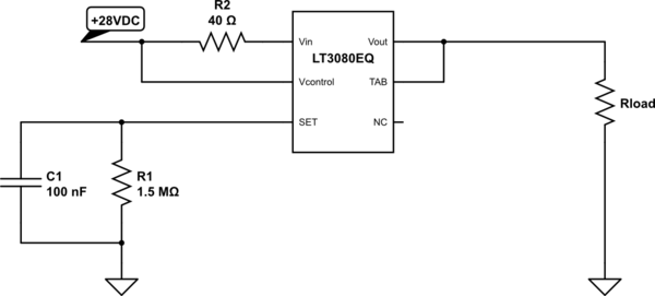
schematic

simulate this circuit – Schematic created using CircuitLab

\$\endgroup\$
1
  • \$\begingroup\$ Is there anything else connected to Vin, such as perhaps a capacitor? If so, it may be a filter. Otherwise, it is either a current limiter, or is designed to help dissipate excess power so the regulator doesn't have to. \$\endgroup\$
    – user57037
    Commented Oct 6, 2015 at 22:52

1 Answer 1

9
\$\begingroup\$

As the datasheet specifies on page 15, "Reducing Power Dissipation" section, it causes power to be dissipated in the resistor rather than in the pass element when the current is high. This will work as long as the resulting voltage drop allows for the dropout voltage of the regulator itself.

\$\endgroup\$
1
  • 1
    \$\begingroup\$ This is not necessarily true, because you can do this with any linear regulator as long as you don't go below the drop-out voltage at the node between the resistor and regulator for the desired maximum current draw. Gonna upvote anyway though! \$\endgroup\$
    – Daniel
    Commented Oct 7, 2015 at 1:00

Your Answer

By clicking “Post Your Answer”, you agree to our terms of service and acknowledge you have read our privacy policy.

Not the answer you're looking for? Browse other questions tagged or ask your own question.