0
\$\begingroup\$

I'm working on a project that uses four L293D motor drivers to control three stepper motors and one DC motor. Separately, there is also a small servo motor. The L293Ds receive a 6V motor supply voltage and 5V logic supply voltage from a MIC29501-5.0WT linear regulator. Both are powered by a regulated 12V 5A supply from a wall outlet. The logic current draw of the L293D has a maximum of 60mA when all outputs are low. The servo motor, which is one of the microservos that you might get in an Arduino starter kit, should draw a maximum of 750mA (it's one of those ones you get in an Arduino starter kit). Additional current draw comes from supplying a couple other chips, which adds 300uA and 900uA respectively. Totaling it all up comes to a little under 1A.

I ran the numbers according the the MIC29501's datasheet, page 24, starting with power dissipation:

Pd = Iout(1.01(Vin - Vout))

Iout is roughly 1A, Vin is 12V, Vout is 5V. So, my total comes to 7.07W

Next is equation 4-2 in the datasheet for calculating the heat sink thermal resistance. Tjmax = 125 degrees C. I kept an estimated maximum ambient temperature of 75 degrees C and have a thermal resistance of 2 degrees C/W since I'm using a T0-220 package, I get a heat sink thermal resistance of:

((125 - 75)/7.07) - (2 + 2) or ((125 - 75)/7.07) - (2 + 0)

Leaving me with heat sink thermal resistance of 3.07 or 5.07 degrees C/W.

The obvious solution is to bolt a really goodheat sink to the MIC29501, or just use a different regulator. That said, I figured this was a good learning opportunity for other solutions, such as using low-value resistors to split heat dissipation between the resistors and the regulator. I'm not sure how viable that solution is at higher current demands, but I'm still curious

\$\endgroup\$
9
  • 2
    \$\begingroup\$ Why not use a switching regulator instead? Then all your problems are gone. \$\endgroup\$
    – Klas-Kenny
    Commented Oct 12, 2023 at 16:33
  • 1
    \$\begingroup\$ Yes, a switching regulator would be a good choice for "a different regulator"!!! \$\endgroup\$
    – TimWescott
    Commented Oct 12, 2023 at 16:46
  • \$\begingroup\$ @Klas-Kenny I noted that was a possibility, but I wanted to hear other solutions too. I probably will go with a switching reg anyway, but other answers could prove helpful in the future \$\endgroup\$
    – E.HP.S
    Commented Oct 12, 2023 at 16:46
  • \$\begingroup\$ Switchers are easy and cheap these days compared to when a TO-220 linear regulator really made sense. Compare the switching regulator solution to the cost of a linear regulator plus its heat sink, the indirect cost of it's extra power consumption and the space taken up by the heat sink. Note that you probably want two separate switching regulators: one for the motor drive and one for the logic supply. This is because motors inject noise back onto their power rails, and you do not want dirty power going into your logic. \$\endgroup\$
    – TimWescott
    Commented Oct 12, 2023 at 17:01
  • 1
    \$\begingroup\$ Problems with L293, L298 and SN754410 H-bridge drivers on a low voltage supply \$\endgroup\$
    – Andy aka
    Commented Oct 12, 2023 at 17:03

3 Answers 3

1
\$\begingroup\$

To answer your question : I suppose you could add some (power) resistors in series to drop some voltage when you are near your max current (at lower current you drop less voltage, but you have also less power, so it should still be fine). But this will be bulky, and still as inefficient as a linear regulator.

Generally speaking, a linear regulator becomes very inefficient as soon as either the voltage difference is big, or the current is "not small".

So usually, I avoid linear regulator is the loss exceeds about 0.5W (usually, if it's above a 20mA or 2V voltage drop, I start thinking if a switching regulator wouldn't be better).

If you are considering medium currents 50mA-2A range, then you can find small switching regulator that just look like a big linear regulator (single 3 pin components). This way, it's as simple as a linear regulator, but (nearly) as efficient as a fully sized switching regulator circuit. For example, at first glance, this one might do for your project : https://www.digikey.fr/en/products/detail/xp-power/VR20S05/13147720

Globally, what I usually do :

  • very small currents <20mA with low voltage difference : linear regulator
  • for currents <1-2A : all integrated switching regulators
  • above 1-2A : either switching regulator modules, or do it directly on my PCB

NB : at work I do low volume high added value products where the development time is usually far more important than the price of the components. For hobby projects it's the same, I don't want to get to complex (excepted if it is really expensive other ways). If you do mass production, then the choice might be completely different, with components cost becoming the main concern.

Excepted for small current, I see only one valid reason to use linear regulators : when you want extremely stable output, and you can't afford the switching noise (as in a lab supply, but then you get 5kg worth of heatsink). Note that in this case, you can also sometimes do a mix : use a switching regulator to step down to 1-2V above your desired voltage, and then add a low drop out (LDO) linear regulator to dissipate just 1 or 2 volts (so far less power) while still maintaining the very smooth output

\$\endgroup\$
1
\$\begingroup\$

The L293Ds receive a 6V motor supply voltage and 5V logic supply voltage from a MIC29501-5.0WT linear regulator. Both are powered by a regulated 12V 5A supply from a wall outlet.

You're not supposed to be linearly regulating anything going into a stepper driver - more or less. The driver will work happily with a 12V supply. Problem solved. The PWM waveform will determine the current flowing through the coils. The voltage does not determine absolute current, only how fast the current is increasing or decreasing. So you can drive those steppers with any voltage their insulation system will take. There's no need to stick to 6V or 12V in particular. Higher voltages will let you spin the motors faster, as you'll have more headroom above the EMF induced in the coils due to motor rotation.

L293 is a rather dumb driver so you need a bit of circuitry around it to actually control the coil current. I wouldn't go that route - there are better integrated drivers that have integrated current sense and current control.

\$\endgroup\$
1
  • \$\begingroup\$ Yeah, parts I'm using are not my first choice, but sometimes you just gotta work with what you have. Besides, you can get a good learning experience out of it, if nothing else \$\endgroup\$
    – E.HP.S
    Commented Oct 12, 2023 at 18:34
1
\$\begingroup\$

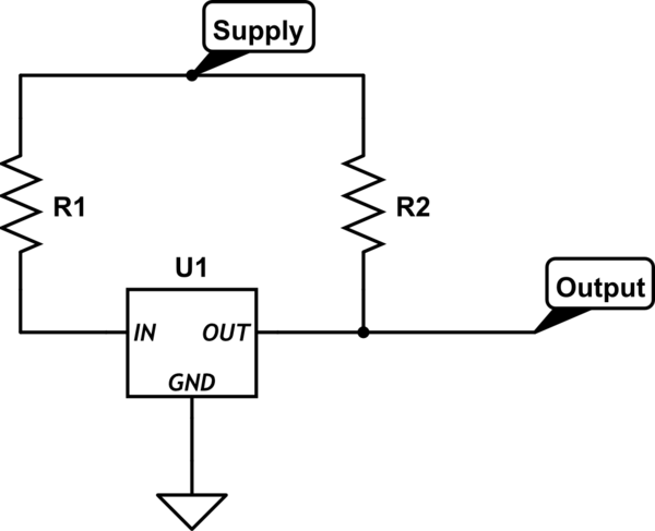
Here's a circuit using resistors to augment the regulator.

schematic

simulate this circuit – Schematic created using CircuitLab

R1 will absorb power when the circuit is drawing current, but it drops the input voltage to the regulator -- when you start pulling enough current that the input drops below the output voltage + dropout, then your regulator will fall out of regulation.

This means that you need to size R1 appropriately for the maximum current draw and the minimum supply voltage.

R2 will deliver current to the output, but it will always do so. This means that if the output circuit draws less current than R2 can deliver, the output voltage will rise above the regulated value.

This means that you need to size R2 appropriately for the minimum current draw and the maximum supply voltage.

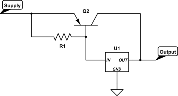
Here's a circuit using a pass transistor to augment the voltage regulator; you'll find this in some older data sheets for regulators such as the 7805. See this post for details.

schematic

simulate this circuit

In this circuit, Q1 will pick up all or part of the load from U1 -- but you're now responsible for circuit stability, and as shown you pretty much lose any ability for U1 to prevent the circuit from overheating when the output is shorted.

If you really want to go there I'll leave it to you to find some good schematics for this.

\$\endgroup\$
3
  • 1
    \$\begingroup\$ You need a collector-base bias resistor in your first diagram methinks. \$\endgroup\$
    – Andy aka
    Commented Oct 12, 2023 at 17:10
  • \$\begingroup\$ @Andyaka I think with a bias resistor this would also not work, but using a PNP would be great. \$\endgroup\$
    – Jens
    Commented Oct 12, 2023 at 20:57
  • \$\begingroup\$ Thanks guys -- fixed. That's what I get for just dumping things out of memory without double-checking. \$\endgroup\$
    – TimWescott
    Commented Oct 12, 2023 at 21:36

Your Answer

By clicking “Post Your Answer”, you agree to our terms of service and acknowledge you have read our privacy policy.

Not the answer you're looking for? Browse other questions tagged or ask your own question.