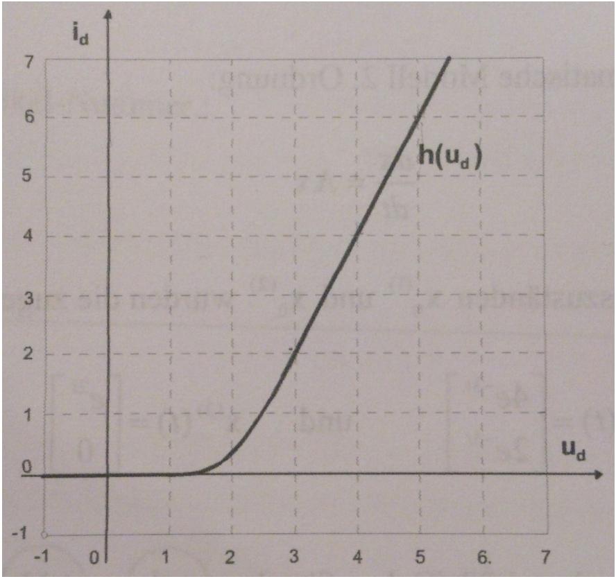
The given circuit is shown in the first picture, whereas the characteristic curve of the diode in the second one. I want to calculate a model in the form of $$\frac{d\textbf{x}}{dt}=f(x,u) \\ \textbf{x}=\begin{bmatrix} i_L & u_c\end{bmatrix}^T$$ for the circuit and then calculate its equilibrium points. I am having problems with this task because I am not sure how to deal with the diode and its function only shown visually. Well, what I did up until now is first, apply Kirchhoff's circuit laws to get two differential equations: $$ u_R+u_L+u_C=u\\ Ri_L+L\frac{di_L}{dt}+u_C=u\\ I: \frac{di_L}{dt}=\frac{1}{L}(u-u_C-Ri_L) $$ $$ i_L=i_C+i_d \\ i_L=C\frac{du_C}{dt}+h(u_d) \\ II: \frac{du_C}{dt}=\frac{1}{C}(h(u_d)-i_L) $$ Next, I tried to calculate the equilibrium points of the system (u=5V, L=1H, C=1F, R=1): $$ I: 5V-u_C-i_L=0\\ II: h(u_d)-i_L=0 \\ I+II:5V-u_C+h(u_d)=0 \rightarrow 5V+h(u_d)=5V+h(u_C)=u_C $$ But with this result I cannot find any solution, so I guess I did something wrong in my calculations, but what and where? Can someone help?
2 Answers
When you added \$I+II\$ you dropped the 2 \$i_L\$'s: $$ I=5V-u_C-i_L=0\\ II=h(u_d)-i_L=0\\ I+II=5V-u_c+h(u_d)-2i_L=0 $$ If you are only interested in the steady-state solution, you can simplify the circuit a lot. In the steady-state, the inductor will behave like a short circuit and the capacitor will behave like an open circuit.
There are the two equilibrium equations:
$$ \text{I}:-u_c-R i_L+u=0 $$
and
$$ \text{II}:h(u_c)-i_L=0 $$
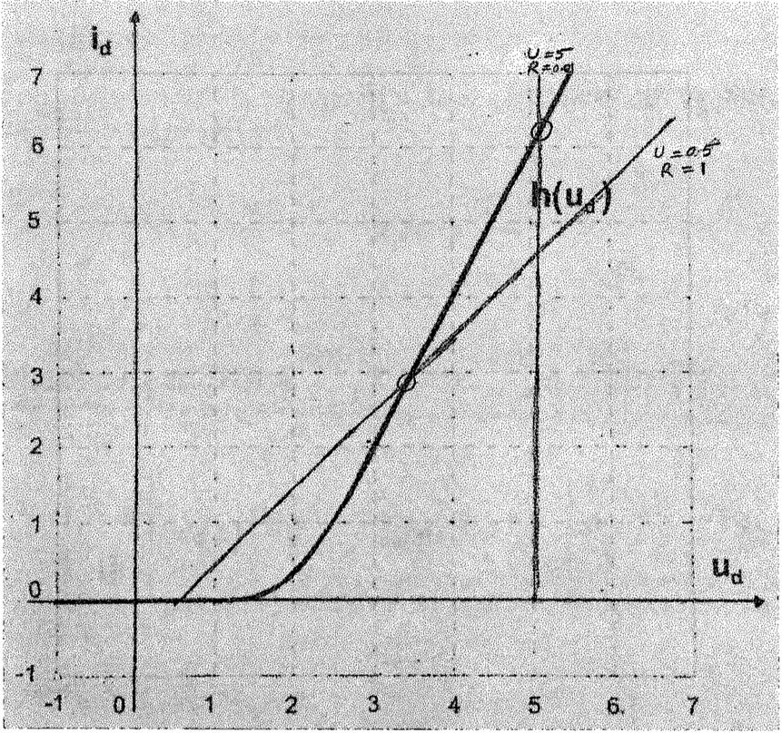
Eliminating \$i_L\$ from the two equations we get the following: $$h(u_c) = \frac{u-u_c}{R}$$
Now we need to choose pairs of \$(u,R, u_c)\$ that satisfy the above equations. These include (approximately) \$(0.5, 1, 3.5)\$ and \$(5, 0.01,5.06)\$, among others, which I have also plotted.


