0
\$\begingroup\$

I need to obtain 5V stable week power supply from a 230VAC power line. I need this as cheap and as small as possible. Fortunately I don't need galvanic isolation and required current is as low as 1-2 mA.

There are no available linear regulators which I could connect directly to rectified mains (the most voltage resistant ICs has up to 450 volts when I need at least 616 volts: 400 * 1,41 + 10% - the device should survive phase to phase connection).

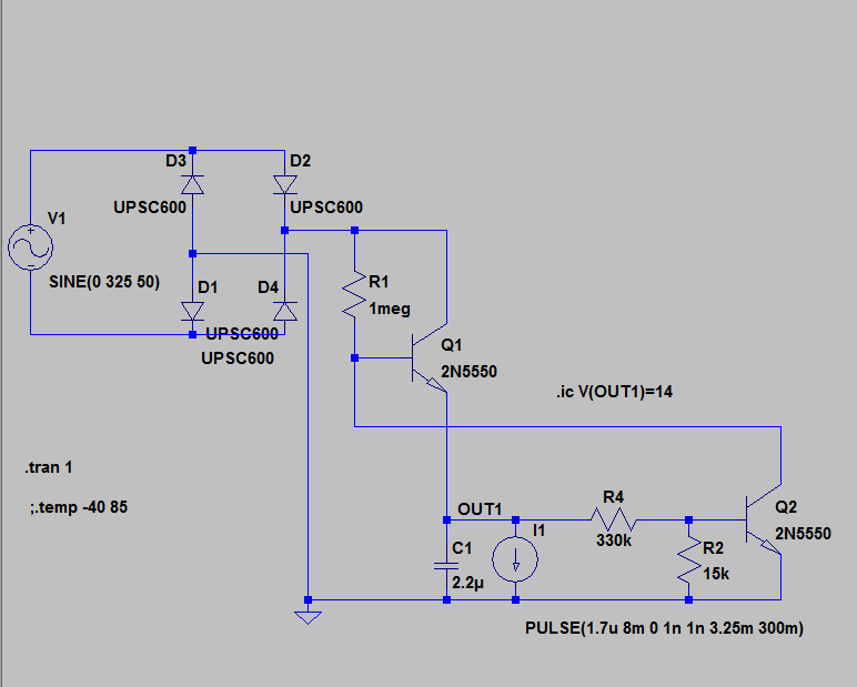
Now I came to this solution:

enter image description here

This schematic works very will.

However I will need conventional linear regulator anyway to provide stable Vcc (output of the schematic above is depends on consumed current and has 100Hz ripples).

If I'd able to put an external switch to regulator I could find the switch with necessary voltage strength and I'd get needed stability.

Is there any solution?

\$\endgroup\$
2
  • 1
    \$\begingroup\$ Of course it has ripples; there's almost no filtering. \$\endgroup\$ Commented Nov 20, 2015 at 9:49
  • \$\begingroup\$ All these are nasty devices and asking for trouble. All will kill yuou easily enough if you let them. Some work :-). Another method is to draw current when Vac is low and turn off the pass element as voltage increases. Also nasty. At such low current you could very probably make a smps with a simple oscillator and small 2 winding transformer. 5v x 2 mA = 10 mW. Say 40 mW in. At 400V that's 0.1 mA. Inductor size can be very small. \$\endgroup\$
    – Russell McMahon
    Commented Nov 20, 2015 at 13:34

2 Answers 2

3
\$\begingroup\$

The most basic approach to this problem doesn't use a bridge rectifer at all but relies on a zener diode current limited by a dropper capacitor: -

enter image description here

The voltage across the zener can be regarded as a square wave with a positive peak at Vz and a negative peak at -0.6V. Using a conventional diode and smoothing capacitor after the zener can give a fairly smooth DC voltage of Vz - 0.7 volts: -
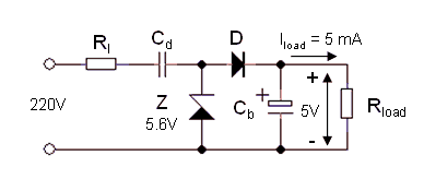
enter image description here

Smoothness is subjective of course and ultimately it depends on the smoothing capacitor value and how much current is taken by the load. You could use a 7.5 volt zener and, on the smoothed output, use an LDO regulator to give a pretty good 5V (if you really need a low ripple supply). I've used the above (without a regulator) to power a microphone, a bit of logic and a triac - it was a sound activated light built into a wall light switch. Ripple wasn't a big deal AND space was limited of course. I used a 5V6 zener as shown.

The resistor in series with the capacitor is there to prevent big surge currents should the circuit be connected to the AC at the peak of the sinewave.

This "full-wave method appears to get used quite often: -
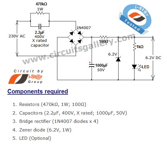
enter image description here

The main idea is the same as the "bridgeless version in that the 2.2uF "drops" the AC voltage without dissipating heat. A zener diode than clamps that voltage. In this design it clamps at 6.2 volts.

It might be worth simulating it to see if the 1000 uF can be reduced in size. I would also consider putting the 100 ohm resistor on the AC side of the bridge and maybe even try this one: -
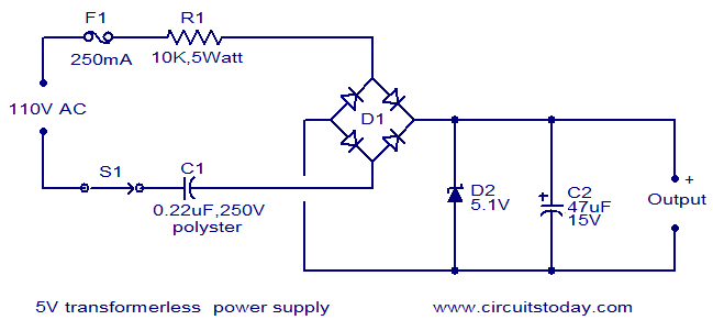
enter image description here

There are quite a few on-line HERE. BTW, the main problem with your design is that the 2N5550 is only rated at 140V max and it inefficiently drops all the voltage and even at 2mA collector current the average voltage across the transistor might be 200 volts and this means 0.4 watts of heat. Capacitor droppers don't have this problem.

\$\endgroup\$
5
  • \$\begingroup\$ Thanks Andy! But this schematic has several drawbacks: 100Ohm resistor will melt :) (under my load it will dissipate more than 4 W), 1000u capacitor is not possible for me (as I need to have it very small, 1000 uF will be a pretty bit electrolytic capacitor) 2u2x400V is also big component :( \$\endgroup\$ Commented Nov 20, 2015 at 10:24
  • \$\begingroup\$ 2mA thru 100 ohms is a power of 0.4 milli watts. Regarding the capacitor, the 2nd design has only 47 uF and is probably more suitable for your current consumption. The big message part of my answer is the link to the google images and the need to simulate a circuit to see how far a design can be stripped back. That's your job! \$\endgroup\$
    – Andy aka
    Commented Nov 20, 2015 at 10:27
  • \$\begingroup\$ Regarding your edit: 2N5550 is the one I found in LTSpice. I plan to use STR1550 which is OK. \$\endgroup\$ Commented Nov 20, 2015 at 10:27
  • \$\begingroup\$ OK! Thanks! Do you have any thoughts regarding the question I've asked (linear regulator with external FET)? \$\endgroup\$ Commented Nov 20, 2015 at 10:29
  • 1
    \$\begingroup\$ No I don't because the above circuits I have shown are tried and tested on regular AC supplies. If you need better regulation than a zener, make the zener voltage 7.5 volts and then post regulate. \$\endgroup\$
    – Andy aka
    Commented Nov 20, 2015 at 10:31
-1
\$\begingroup\$

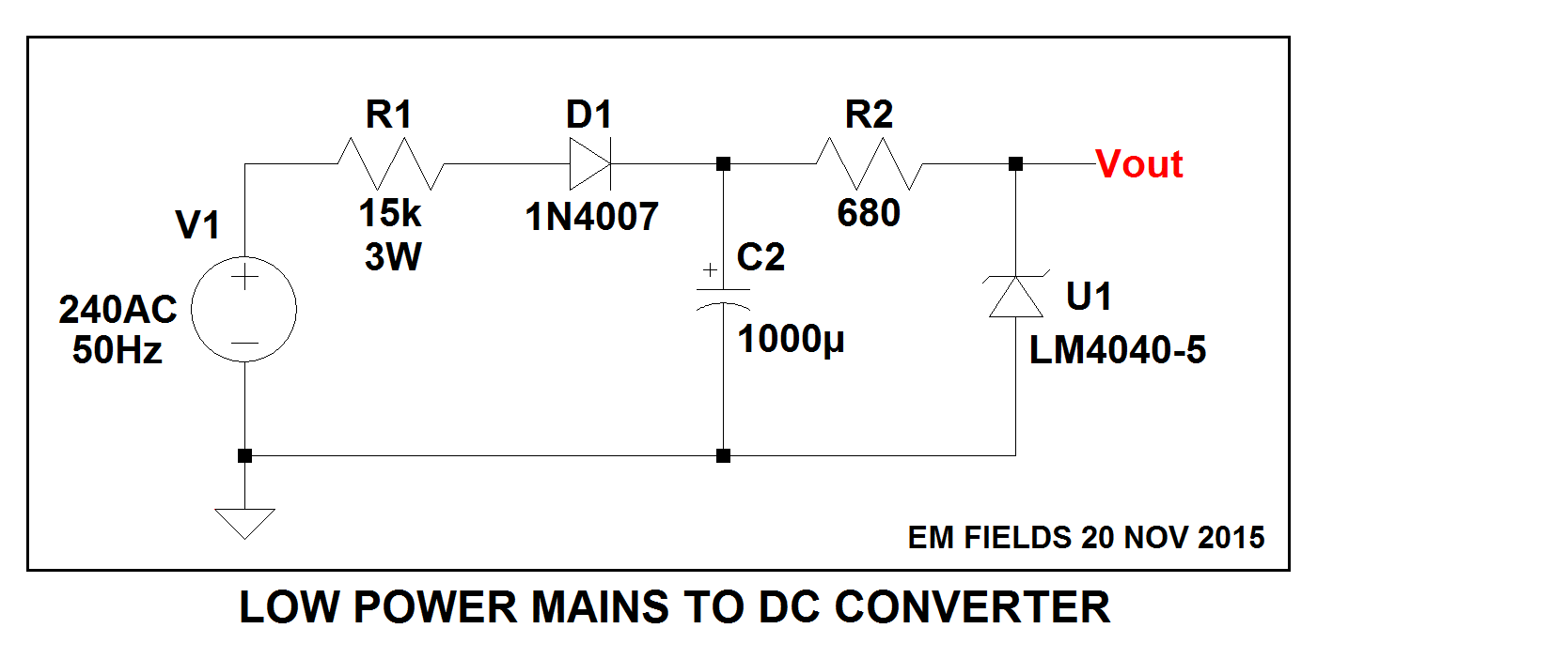
Hard to get simpler than this:

enter image description here

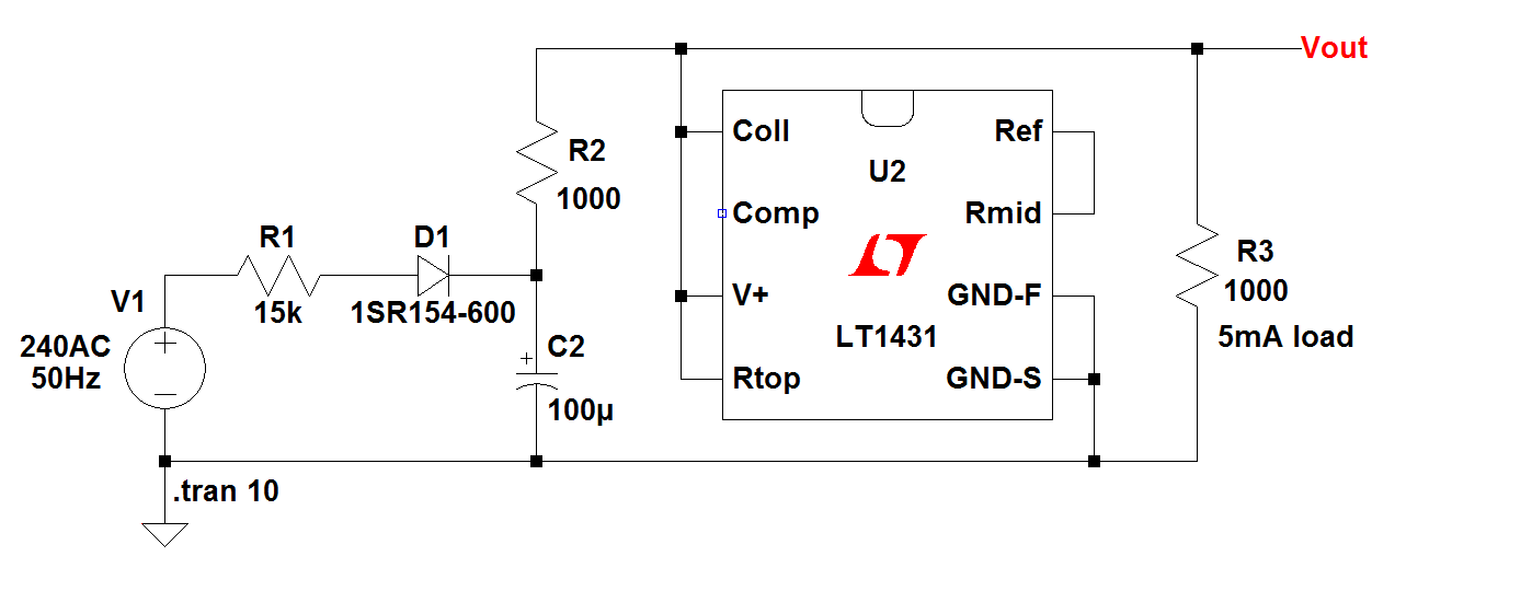
Just for grins, if you want to play around with the circuit. here's it is using an LTspice shunt regulator and LTspice library parts followed by the circuit list.

Enjoy!

enter image description here

Version 4
SHEET 1 1120 680
WIRE 432 -64 320 -64
WIRE 832 -64 432 -64
WIRE 912 -64 832 -64
WIRE 320 -16 320 -64
WIRE 432 0 432 -64
WIRE 464 0 432 0
WIRE 752 0 720 0
WIRE 752 64 752 0
WIRE 752 64 720 64
WIRE 832 64 832 -64
WIRE 80 112 32 112
WIRE 208 112 160 112
WIRE 320 112 320 64
WIRE 320 112 272 112
WIRE 432 128 432 0
WIRE 464 128 432 128
WIRE 752 128 720 128
WIRE 32 144 32 112
WIRE 320 160 320 112
WIRE 432 192 432 128
WIRE 464 192 432 192
WIRE 752 192 752 128
WIRE 752 192 720 192
WIRE 32 256 32 224
WIRE 320 256 320 224
WIRE 320 256 32 256
WIRE 752 256 752 192
WIRE 752 256 320 256
WIRE 832 256 832 144
WIRE 832 256 752 256
WIRE 32 304 32 256
FLAG 32 304 0
FLAG 912 -64 Vout
SYMBOL voltage 32 128 R0
WINDOW 0 -42 5 Left 2
WINDOW 3 24 96 Invisible 2
WINDOW 123 0 0 Left 2
WINDOW 39 0 0 Left 2
SYMATTR InstName V1
SYMATTR Value SINE(0 340 50)
SYMBOL res 336 80 R180
WINDOW 0 -38 64 Left 2
WINDOW 3 -50 27 Left 2
SYMATTR InstName R2
SYMATTR Value 1000
SYMBOL polcap 304 160 R0
SYMATTR InstName C2
SYMATTR Value 100µ
SYMBOL References\\LT1431 592 96 R0
SYMATTR InstName U2
SYMBOL diode 208 128 R270
WINDOW 0 32 32 VTop 2
WINDOW 3 0 32 VBottom 2
SYMATTR InstName D1
SYMATTR Value 1SR154-600
SYMBOL res 176 96 R90
WINDOW 0 0 56 VBottom 2
WINDOW 3 32 56 VTop 2
SYMATTR InstName R1
SYMATTR Value 15k
SYMBOL res 816 48 R0
WINDOW 0 46 46 Left 2
SYMATTR InstName R3
SYMATTR Value 1000
TEXT -80 168 Left 2 ;240AC
TEXT -72 192 Left 2 ;50Hz
TEXT 38 280 Left 2 !.tran 10
TEXT 848 160 Left 2 ;5mA load
\$\endgroup\$
7
  • \$\begingroup\$ You're right: this is simple :) However I don't need it simple, I need it cheap and small. Power of R1 will be about 2W: it is a big and hot resistor) and 1000uF capacitor is also big. Could you make some input on the question I asked? \$\endgroup\$ Commented Nov 20, 2015 at 13:20
  • \$\begingroup\$ @RomanMatveev: Here's the data sheet for the resistor. \$\endgroup\$
    – EM Fields
    Commented Nov 20, 2015 at 13:52
  • \$\begingroup\$ Ups... Missed the link! Please edit you comment :) \$\endgroup\$ Commented Nov 20, 2015 at 14:02
  • \$\begingroup\$ @RomanMatveev: Here's the data sheet for the resistor. Check its dimensions. That 1000 uF cap has been changed to 100 uF, and you could get by with less, probably, if push came to shove. Also, do you think your circuit is going to cost less and dissipate less power once you get all the stuff into it that you need if you do it your way? Good luck. Finally, I did respond to your pleas for help by providing you with a viable, sensible solution, and what do I get back? A slap. Sorry, it won't happen again. \$\endgroup\$
    – EM Fields
    Commented Nov 20, 2015 at 14:10
  • \$\begingroup\$ A slap?! I can not figure out how my comment can be treated as a slap. I'm sorry anyway, I have no intention to hurt you. Probably it is due to my poor English. However I start to think that I should put less information to my questions on this site as I often receiving the answer pretty far from the main question. And this is bothering me a lot :( \$\endgroup\$ Commented Nov 20, 2015 at 14:32

Your Answer

By clicking “Post Your Answer”, you agree to our terms of service and acknowledge you have read our privacy policy.

Not the answer you're looking for? Browse other questions tagged or ask your own question.