2
\$\begingroup\$

I'm designing a DC Lab Power Supply; the voltage regulation circuit looks like this:

enter image description here

I'm developing the BOM, component by component, and next in line is specifying the capacitor in the feedback loop for the op amp, C1 in this schematic.

As I'm going through the selection of specific components, I've developed a new appreciation for the diversity of available capacitors and the relative complexity of what I originally thought was a pretty straightforward component type. So my dwelling on this particular component is as much for the learning opportunity it presents as the desire to pick the right item for this specific case.

My PCB is SMD wherever possible, and I'm inclined to believe a garden-variety 0805 X7R would do the job just fine. However, I've learned they can have surprising behaviors depending on, for example, the voltage applied, so wanted to get the perspective of more experienced designers.

The design of the feedback loop itself was by far the biggest time investment in the circuit overall. I had to refresh my foggy recollection of Body plots, transfer functions, op amp particulars, etc. And it took me quite a few tries to get it this right (and understand why it worked then :). So I'm inclined to think if there's anywhere in the overall where the capacitance in critical that this would be it.

So my question is: Is a regular surface-mount ceramic cap the right choice for using in this feedback loop? Or should I be thinking something a little fancier, like perhaps a film capacitor of some type?

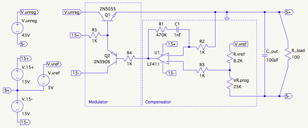
\$\endgroup\$
2
  • \$\begingroup\$ Oh no, not this circuit again LOL. \$\endgroup\$
    – Andy aka
    Commented Dec 2, 2015 at 9:47
  • \$\begingroup\$ Bwah-hah-hah-haha! :) It's actually become substantially more elaborate now after adding in the constant current and CC/CV mode indication LEDs etc., but I thought I'd keep it simple and reuse a more focused precursor schematic :) \$\endgroup\$
    – scanny
    Commented Dec 2, 2015 at 18:47

3 Answers 3

3
\$\begingroup\$

DC bias effects have already been noted (there is an excellent application note from Murata on this). This link appears to be broken; this FAQ page may be of use.

C0G, although marginally more expensive, bring other things to the table, and in a feedback loop such as yours (I am designing some right now in an interesting application switching a few hundred volts that requires a linear ramp), I want to have a part that will remain at its rated capacitance across bias, time and temperature.

C0G: No DC bias effect from most manufacturers (this has to do with the material used). This is definitely true of AVX, Murata and Johnson.

No capacitor ageing

Tempco <= 30ppm: This will be important if the power supply box heats up significantly.

Compare that to X7R and you will find that in a control loop, C0G is the best choice in a ceramic. I would not normally need to use a better part than that.

I am actually using a 1nF C0G, 50V, 5%, 0603 part from AVX (but all the usual suspects have them).

\$\endgroup\$
3
  • \$\begingroup\$ Very useful answer Peter, it definitely makes sense to me to use a C0G version here now that you've explained it. I'll order some up :) \$\endgroup\$
    – scanny
    Commented Dec 2, 2015 at 19:17
  • \$\begingroup\$ appnote 404 not found \$\endgroup\$
    – Jason S
    Commented Dec 28, 2016 at 17:20
  • \$\begingroup\$ Year old link - I will see if I can find the new location. \$\endgroup\$ Commented Dec 28, 2016 at 17:23
3
\$\begingroup\$

The hazard with some ceramic capacitors are that they lose capacitance as the voltage goes up, and as the temperature goes up. Some under conditions within the data sheet T and V ratings can drop to 25% of their nominal capacitance. The worst are the very high value, so >1uF caps in small packages where you look at them and think 'how the mike did they cram all that capacity into that? The answer is, by making other compromises on the dielectric material.

Used in that C1 position, losing some C would result in the break frequency of that RC moving up from your design of 340Hz. If your stability margin is so small that you need high precision on that time constant, then I suggest you improve your margins.

I don't recall which of temperature and voltage spec designations like X7R leave underspecified, but as you have asked this question for your education, that's fine. I will simply warn you, and you can go digging for the information. You will need to dig deep. I won't say the manufacturers try to hide this stuff, but they sure don't make it easy to find. You will probably need to look in the material, rather than the capacitor, data sheets.

Amongst the main choices for materials are
NP0 - very stable, but only very low values. You might find a 1nF in that.
X7R - expect +/- 15%, only goes to mid values
X5R and Y5R - possibly -75% under some conditions, read the data sheets for the specific capacitor value, package (yes, even the package), voltage , manufacturer and material very carefully.

Keep your max voltage well below the rated voltage. At 1nF X7R, you should not have any problems.

\$\endgroup\$
1
\$\begingroup\$

The type isn't critical, as long as it meets your tolerance needs.

Be aware that ceramics (not sure they are available so small) lose >> 20 % (to 50 % or more ) of their capacitance as the applied voltage reaches their rating. To avoid this, you can use a cap that is rated at a higher voltage than you need.

On your circuit -- if your + and - 15 V supplies don't come up properly, is there any possibility that your output will become unregulated ? The 1k will turn on Q1, but requires the opamp to turn it off...

\$\endgroup\$
1
  • \$\begingroup\$ I was wondering about the unregulated moments question myself, and had actually observed it on shutdown on an earlier prototype. The negative rail was going down before the positive one, and so in certain load situations there would be a voltage/current pulse during shutdown. It went away when I adjusted the filter caps on the bias supply to make the negative one bigger (it naturally provides more current in the circuit). But I have to say I don't completely understand why there's not a complementary pulse on startup :) I'll test again before I wrap up the PCB. \$\endgroup\$
    – scanny
    Commented Dec 2, 2015 at 18:57

Your Answer

By clicking “Post Your Answer”, you agree to our terms of service and acknowledge you have read our privacy policy.

Not the answer you're looking for? Browse other questions tagged or ask your own question.