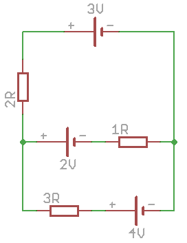
What would the current flow be through the 1 ohm resistor? They are constant voltage sources, not batteries.

OK, since the OP says it's not homework...
As @Olin has pointed out, you have three voltage sources, each in series with a resistor, that are all connected in parallel.
The easiest way to analyze this is via Thevenin and Norton equivalent circuits. The (voltage source + series resistance) subcircuits which are Thevenin equivalents (presumably to be a first-order approximation to a battery), can be transformed to Norton equivalents:
3V + 2 ohm series -> 1.5A || 2 ohm, since 3V/2ohm = 1.5A
2V + 1 ohm series -> 2A || 1 ohm
4V + 3 ohm series -> 4/3A || 3 ohm
Then, the Norton equivalents can be paralleled easily by adding the currents and computing the parallel equivalent resistance: 1.5A + 2A + 4/3A = 29/6A; 2 ohm || 1 ohm || 3 ohm = 1/(1/2+1+1/3) ohm = 1/ (11/6) ohm = 6/11 ohm.
To get the open circuit voltage, compute the Norton current * Norton resistance = 29/6A * 6/11V = 29/11V = 2.636V
To get the current flowing through the 1 ohm resistor and 2V source, just compute (29/11V - 2V) / 1 ohm = 7/11A (= 0.636A)
Assume for now that the batteries are perfect voltage sources. In that case you can solve for the Thevenin equivalent to get the voltage on the left side with respect to the right side.
Let's lump the bottom two into a single Thevenin source first. The impedance will be 3Ω//1Ω = 750mΩ, and the voltage 2.5V. Now combine that source with the top one which is 3V with 2Ω impedance.
I'm giving you a rough idea of the method but not the actual answer since you wouldn't learn anything from this homework assignment otherwise.
If this is supposed to represent real batteries, then we need more specs. By inspection you should be able to see that at least one cell will have reverse current thru it. That leads to all sorts of questions. I suspect, however, that your instructor drew batteries although intending you to do the computation as if they were perfect voltage sources.
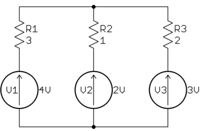
Now that you've clarified the batteries in your schematic are really ideal voltage sources, it simplifies the problem and makes a definite solution possible. To start with, I would redraw the schematic as follows:

That should make it much easier to visualize what is going on as apposed to your schematic which seems intended to obscure. The problem is to find the current thru R2.
One way to attack this is to compute the voltage at the top node. Then you can subtract the voltage of V2 to find the voltage accross R2. Basic Ohm's law then tells you the current thru R2.
This is your homework problem, so please report back what you find, or ask a specific question about what you're stuck on. We aren't just going to solve it for you.
It would flow until all the batteries are of the same voltage.
Once they are all at the same voltage, current will stop flowing since all the batteries have the same voltage compared to ground.
The resistors do not do anything in this situation other than limit the current flow when the batteries are first plugged together in parallel like that. After all the batteries equalize voltages then no more current flows anywhere.
homeworkis a metatag which doesn't do that, that's why it's deprecated. If it's homework that can be indicated in the question's body. \$\endgroup\$