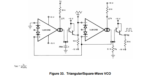
I am trying to work through the math of the following schematic pulled from the LM13700 datasheet:
I can certainly hook this up and mess with the values to change the frequency range to my liking (and I will) but I am more interested in working out the math formula using the values provided in the data sheet at this point.
Problem: Using the values in the schematic, I am unable to come up with the same frequency range (f_OSC) that the datasheet describes when I put the numbers into the formula.
The formula for fig 33 in the data sjeet is: f_OSC = I_C/(4*CI_AR_A)
Sorry for the plain text equations, MathJax editor doesn't appear to be available right now.
According to the Datasheet, using the values shown in the schematic above, if I plug in ~0 < I_C < .001 Amps, I would expect a resulting frequency of 2Hz < f_OSC < 200kHz. However, plugging in the high end value (.001A) I get more than double what I should on f_OSC. I'll try to show my work below in hopes it will point out an obvious error to those more mathematically inclined:
f_OSC = (.001 Amps) / (4*(.0000000002 Farads)*(30 Volts/51000 Ohms)(5100 Ohms))
f_OSC = (.001 Amps) / (4*(.0000000002 Farads)*(.00058 Amps)(5100 Ohms)
f_OSC = .001 / (4*.0000000006) Farad*Ohms
f_OSC = .001 / .0000000024 Farad*Ohms (Seconds?)
f_OSC = 1 / .0000024 Seconds
f_OSC = 416,666.67 Hz
As for the .00058 Amps you see in the denominator for part of the equation above, I used 30 Volts to divide down the resistance instead of +15 Volts because the pin that receives I_C follows a path to -15 Volts, not Gnd. So the total potential difference there is ~30 Volts.
Question: Can someone please help me understand why my math shows an output f_OSC = 400KHz for an input current of 1 milliAmp when the data sheet indicates the answer should be 200KHz for the same input? Did I solve the equation above correctly or perhaps misinterpret the information in the datasheet?


