4
\$\begingroup\$

I am developing a program to send and receive sigal to my circuit and pc. Actually I have to count the pulses or (frequency of high pulse) generated from a 555 timer IC in my circuit. When I connect a input pin of Parallel port to the ground pin or simply to a casing of the system it produce a input signal. I used transistor in the hardware side which let connect input pin to the ground on the production of High pulse. I think it is not a good method to do so.

Is there any way to do it directly by sending voltage to parallel port input pin?

What amount of current and voltage is required?

I am using 2x1.5 volt AA size batteries to supply power to the circuit.

\$\endgroup\$

2 Answers 2

3
\$\begingroup\$
  • What Oli says

  • Plus

    The parallel port notionally uses TTL levels. The actual levels accepted my vary in modern implementations. Theoretically, if you are driving a pin which is set to input then the "high" level can be as low as 2 Volts.

    If the pin you are driving is feinitely an input you should be able to drive it with a 555 directly (see below re voltages).
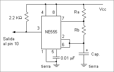
    This '555 to parallel port interface appication seems to do exactly what you want. See circuit diagram below and do look at the above referenced page.

enter image description here

  • If you are using 2 x non rechargeable AA cells the available voltage will be about 3V max when the batteries are new and as little as under 2 Volts when the battery is almost dead. A circuit could be built which operates correctly on new batteries BUT this will get marginal as batteries are depleted.Driving the port directly with 2V is marginal at best.

  • Using a transistor as a "pull down" allows th port to float high when the transistor is off. Even if you only have 2V available the pin can float to whatever voltage is available from the port - say 5V. Expecting TTL pins to float high without a pullup is bad design practice but worked well with real TTL and was commonly done. Wity modern implementations in aCMOS master IC the pin MAY NOT float high properly without a pullup resistor. Finding a pin on the port which i ALWAYS high (nominally 5V) and connecting a say 10k resistor from there to the input pin may help.

  • You say you are using a "555". Is it also running from the same 2 batteries? Some 555's require about 4.5V minimum to operate whole others will operate on less than a volt. Check the spec sheet to be sure what voltage the device that you have will operate on.

\$\endgroup\$
3
\$\begingroup\$

Why do you think this is not a good method?

This is the standard way to use an open drain/collector line. You would not want to put a low impedance "high" on the line as it could create a conflict if the other side is trying to pull the line down, which would effectively short your output to ground. Rather you just have the open collector, which cannot source current (only sink it)

The voltage is probably +5V (measure with a multimeter to confirm), so since your circuit is running at 3V this is another reason to avoid interfacing "directly". Similarly for signals going from PC to your circuit you will probably need to level shift (e.g. 5V -> 3V) to avoid problems. Or run your circuit from the same voltage.

Here is a half decent page on parallel ports which gives some details on the various signals and the technology used. I would spend a bit of time Googling/reading, as you will risk stressing or even damaging circuit/parallel port if you get it wrong.

\$\endgroup\$
4
  • \$\begingroup\$ He may need a pullup in specific cases. \$\endgroup\$
    – Russell McMahon
    Commented Oct 21, 2011 at 0:29
  • \$\begingroup\$ @RussellMcMahon - I was assuming there was a pullup on the (open collector) control pins (and the OP was using a control pin - should maybe have confirmed this..) The page I linked to mentioned something about this - of course if the data lines are bi-directional then driving one of them directly instead should be fine (taking into account the issues you mention in your answer) \$\endgroup\$
    – Oli Glaser
    Commented Oct 21, 2011 at 6:59
  • \$\begingroup\$ No criticism implied. And chances are it doesn't need a pullup. Just trying to 'cover all bases'. TTL = no pullup = OK in most practice. CMOS reinterpretations of a parallel port may add fun. \$\endgroup\$
    – Russell McMahon
    Commented Oct 21, 2011 at 10:23
  • \$\begingroup\$ @Russell - none taken :-) you are quite right to cover all bases. It's been years since I used a parallel port so I was going (mainly) from the information I scanned through. \$\endgroup\$
    – Oli Glaser
    Commented Oct 21, 2011 at 13:12

Your Answer

By clicking “Post Your Answer”, you agree to our terms of service and acknowledge you have read our privacy policy.

Not the answer you're looking for? Browse other questions tagged or ask your own question.