0
\$\begingroup\$

enter image description here

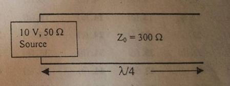
Consider a 300 Ω lossless line operating at 1GHz which is connected to a source of 10V and impedance of 50 Ω.

What is the magnitude of voltage at the open circuit end?

My attempt:

At the input side the voltage (\$V_o\$) is 0V and the current at the sending end is given by:

$$I_o = \frac{10}{50} = 0.2A$$

and

$$V_o = 0V$$

Now the positive going voltage amplitude (\$V_+\$) is given by:

$$V_+ = 0.5 (V_o + I_o \cdot Z_o)$$

The negative going voltage amplitude (\$V_-\$) is given by:

$$V_- = 0.5 (V_o - I_o \cdot Z_o)$$

where \$Z_o\$ is the characteristic impedance.

Thus, \$V_+ = 30V\$ and \$V_- = -30V\$.

Now the voltage at any point on the line is given by:

$$V(z) = V_+^{-bz} + V_-^{+bz}$$

where \$bz\$ is the electrical length of the line.

Thus at Load end \$V(\lambda/4) = j60 \cdot sin(bz) = j60\$

Is it possible to get a voltage of 60V at the open end while you are applying only a source of 10V? Does reflection at open end has anything to do with this?

\$\endgroup\$
4
  • \$\begingroup\$ Are you talking about a DC voltage of 10V being applied and you are wanting to know how this propagates and eventually settles down at the far end? \$\endgroup\$
    – Andy aka
    Commented Jan 18, 2016 at 13:05
  • \$\begingroup\$ Look at the picture, what is the impedance at the end of the line? \$\endgroup\$
    – johnnymopo
    Commented Jan 18, 2016 at 15:39
  • \$\begingroup\$ Is 'input side' the same place as 'sending end'? V+ and V- refer to forward and reflected waves, not to positive and negative half-cycles of the sinusoid. You need to clarify exactly what you're asking. \$\endgroup\$
    – Chu
    Commented Jan 18, 2016 at 17:37
  • \$\begingroup\$ its a 10 GHz signal that we are sending, yes the input side is same as the sending end and the open circuit end is the load end.@Andyaka @Chu \$\endgroup\$ Commented Jan 19, 2016 at 3:58

2 Answers 2

2
\$\begingroup\$

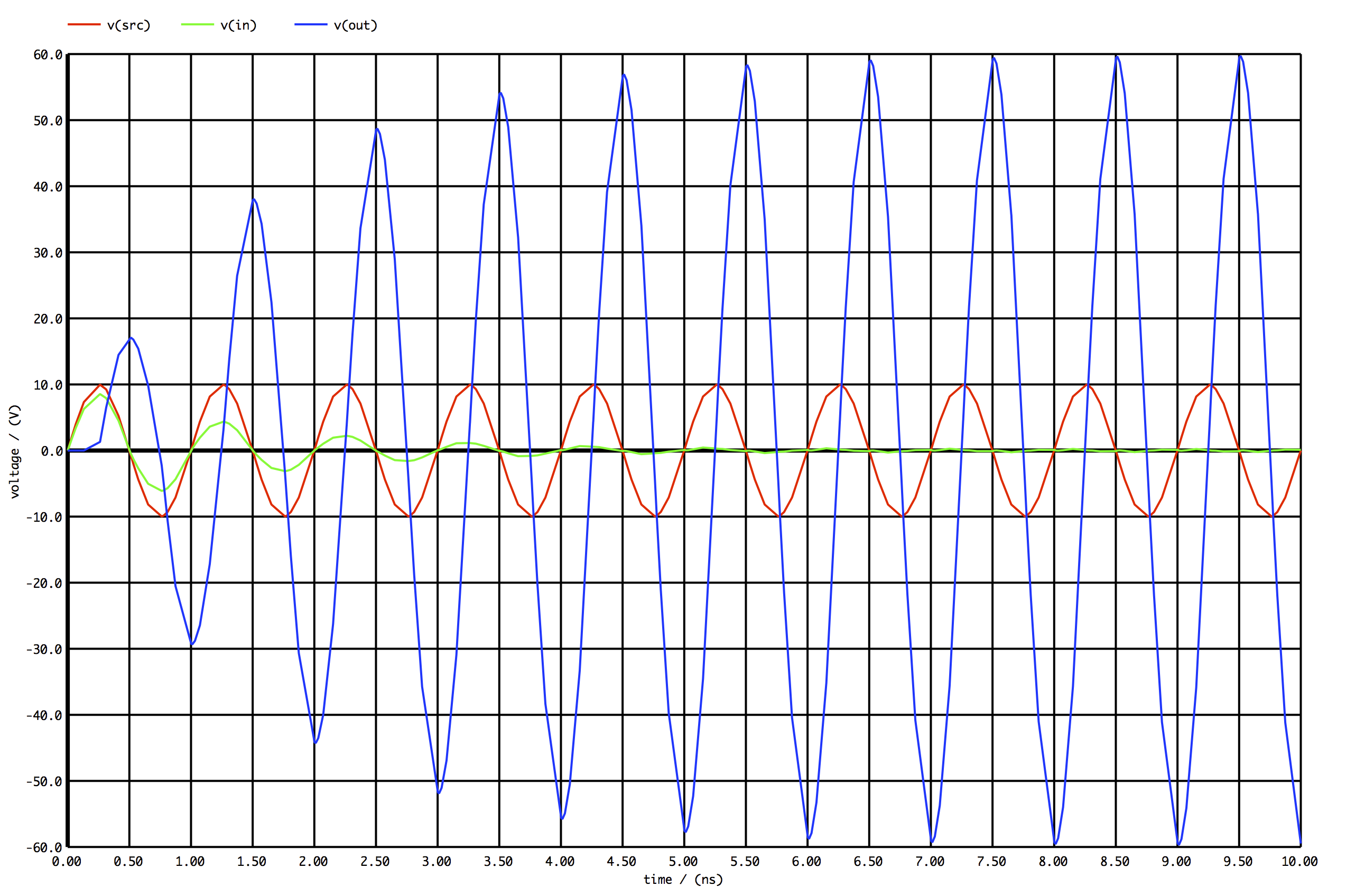
Yes, 60v is what you would see at the end of the quarter-wavelength transmission line. This is due to the multiple reflections back and forth from the open at the end of the transmission line and the impedance mismatch at the input (300-ohm to 50-ohm). This effectively is creating a standing wave giving you 300/50 = 6 multiplication in voltage at the end of the quarter-wavelength and 0V at the input after a few cycles.

You can see the response below

transmission line transient behavior

\$\endgroup\$
1
  • \$\begingroup\$ I hope this is not practically possible, the loss across the line will surely play a major role in determining the voltage at open end, if you agree ,can you please add on what happens when its a lossy line. \$\endgroup\$ Commented Jan 19, 2016 at 4:01
0
\$\begingroup\$

γ = a + jβ a = 0 γ = jβ

Propagating wave

v = VI e-rz + VR erz

No change in the voltage at the open end it will same,

vr = 10 volt.

\$\endgroup\$

Your Answer

By clicking “Post Your Answer”, you agree to our terms of service and acknowledge you have read our privacy policy.

Not the answer you're looking for? Browse other questions tagged or ask your own question.