2
\$\begingroup\$

I have a simple setup when I have to read analog values from a light sensor, and I need to put it far away from the arduino (several meters away). I want to know how can I create a wired reliable connection from the arduino to the sensor.
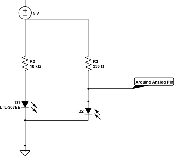
schematic

simulate this circuit – Schematic created using CircuitLab

Here is the function that activates the system:

void photoResistorActivation () { int photoResistor = 1024 - analogRead(PHOTO_RESISTOR_PIN); if (DEBUG) { Serial.println (photoResistor, DEC); } if (photoResistor >= LIGHT_THRESHOLD) { personDetected = false; } else { if (personDetected == false) { trigger = true; personDetected = true; } } }

Edit: I have received valuable feedback in the answers about how to avoid noise, but I want to clarify that I'm asking about physical connection (cables, connectors and so on). What kind of cables should I use? Jumper cables?

Thank you

\$\endgroup\$
6
  • 1
    \$\begingroup\$ What do you want to measure exactly? The "light sensor" at the given link is a IR detector. Do you need a real analog value or just on/off at a given threshold? \$\endgroup\$
    – Stefan
    Commented Jan 18, 2016 at 20:31
  • \$\begingroup\$ I wrote the code and is working, I just want to know how to physically connect the sensor to arduino \$\endgroup\$ Commented Jan 18, 2016 at 20:44
  • \$\begingroup\$ To repeat @Stefan's question. Do you need to measure an analogue value, or do you only need an off/on against a threshold? Our answer depends on the type of value you need. Please clarify your question; post the schematic of how you are using it, and a piece of the code that is using it. \$\endgroup\$
    – gbulmer
    Commented Jan 18, 2016 at 20:54
  • \$\begingroup\$ I need on/off, updated question with code \$\endgroup\$ Commented Jan 18, 2016 at 20:57
  • \$\begingroup\$ The nature of the light sensor and your amplifier circuit are really very necessary to answer this question. In fact, the code and the arduino aren't very relevant at all. \$\endgroup\$ Commented Jan 18, 2016 at 21:18

2 Answers 2

4
\$\begingroup\$

I would consider using some capacitors, clamping diodes, and output resistors very close to the arduino.

The long wires will have capactive and inductive loads. Bumps to the wire will create noise spikes.

  • The output resistors (input to the arduino) will limit the spike based on the current surge (should be low, 10k resistor should be fine).
  • The capacitor will stabilize the voltage, select the capacitor value based on a low pass filter RC equation and the expected frequency of the light changing (f = 1/2*piRC). If it's just ambient light in a room go with 10uF or whatever is available, if its a strobing diode, calculate the filter value.
  • For the clamping diode, pick a fast response time diode that clamps at a little over 5V so the noise spikes, and ESD, from tapping the wire doesn't kill the input pin on your arduino. The P6KE6V8CA should do the trick.
\$\endgroup\$
2
  • \$\begingroup\$ Connect the 'output' (anode) of the phototransistor to the resistor and to the input of the arduino. Connect the cathode to ground. \$\endgroup\$ Commented Jan 18, 2016 at 20:57
  • 1
    \$\begingroup\$ Any cables will suffice, assuming they are metal and conductive. Don't you have scrap wires laying around? Gauge should not matter for this low power application. Assuming you are going to use this for a while, you may want something you can solder so it doesn't fall apart or fail on you. \$\endgroup\$ Commented Jan 18, 2016 at 21:27
0
\$\begingroup\$

Your question is a bit vague.

The best solution would be to put an ADC behind the sensor, since digital transmission is a lot more resitant against distortion. If this is possible you might want to transmit it even differentially (invert the signal and output either plus and minus your high level or 0).

If this is not possible you want at least a twisted pair cable or a shielded cable to reduce the distortion. The best connection should be a BNC connector on the board and a coax cable.

Also if you can't put an ADC behind the sensor, you might still want to amplify your analogue signal depending on what the sensor outputs.

\$\endgroup\$

Your Answer

By clicking “Post Your Answer”, you agree to our terms of service and acknowledge you have read our privacy policy.

Not the answer you're looking for? Browse other questions tagged or ask your own question.