I am working on a pulsed induction linear motor (aka multi-stage coil gun) as a hobby project. I'm more of an electronics kind of guy so this is an opportunity for me to become more familiar with power electronics.
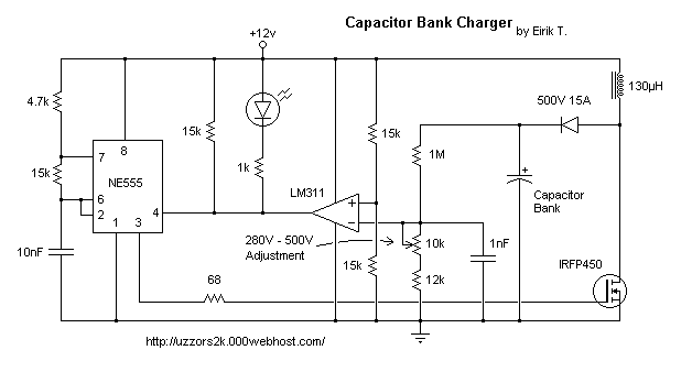
The first component I need to build is a 12V->500V booster circuit to charger a capacitor bank. I found the schematic below here.

I modeled the circuit as well as I could in LTSpice and I'm seeing the expected voltages. However, the currents I'm seeing through the inductor & MOSFET are way over the max ratings. The inductor is rated for 4A (continuous) and the MOSFET is rated for 13.5A (continuous), yet both are seeing currents of 15A RMS. I am well aware how dangerous things get at voltages this high so I am very skeptical about this schematic.
I don't have the exact components in my library but I tried matching everything as closely as possible. I set the series resistance of the inductor to the datasheet value and chose a MOSFET with similar drain-source resistance (ON). I included the series resistance of the 12V battery as well.
So my questions are:
- Am I being overly cautious?
- Am I forgetting to model something?
- If the schematic is wrong, what is the best way to reduce the current? MOSFET with higher series resistance (which I'm guessing results in higher power dissipation), larger inductor?
