1
\$\begingroup\$

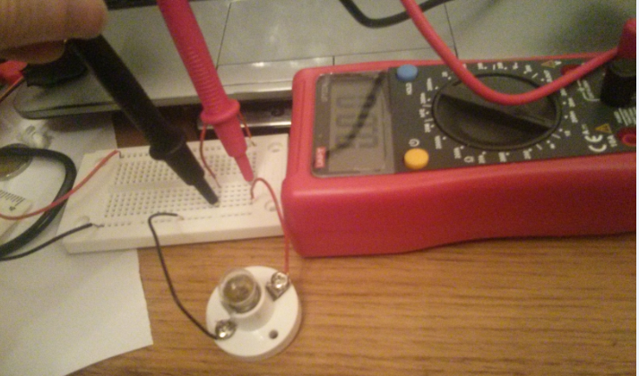
It lights here with no multimeter, this is fine

enter image description here

But if I replace one of those wires with the multimeter, connecting the multimeter in series, then the bulb doesn't light. I am wanting to measure current of course, but from what I understand, the bulb should be lighting up. I am as you see, getting a 0 reading so for some reason the circuit isn't happening.

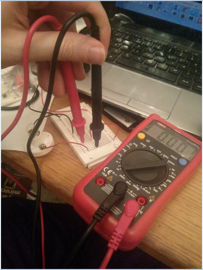
enter image description here

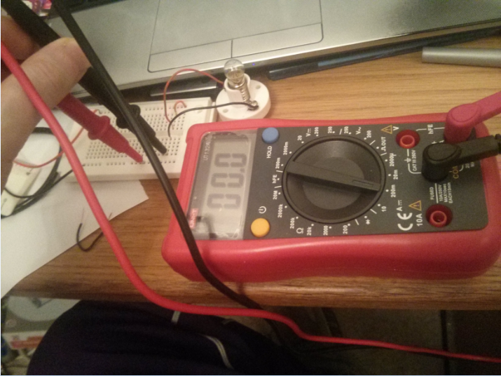
Here's another picture in case the above one wasn't clear enough

enter image description here

Why is the bulb not lighting?

The multimeter is able to measure voltage and resistance ok. I trued adding the wire, so the bulb lit, and putting the probes across the bulb and it measured the voltage, and I tried putting taking a resister and putting a probe on each leg and it measured that, so it's just this issue trying to measure current. I'm a complete newb so most likely I'm doing something simple wrong.

Added

One answerer mentions that I had the dial set to 10A. I also tried the dial in 200m 20m and 2000 micro, and it still said 0 and the bulb didn't light.

Another answerer suggested a continuity test.. I am not entirely sure how.. one video on youtube showed showed a guy pointing his dial to what he described as a wifi type symbol and then tapping the probes together and getting a beep.. I don't see such a symbol and I don't get a beep on any setting of the dial.

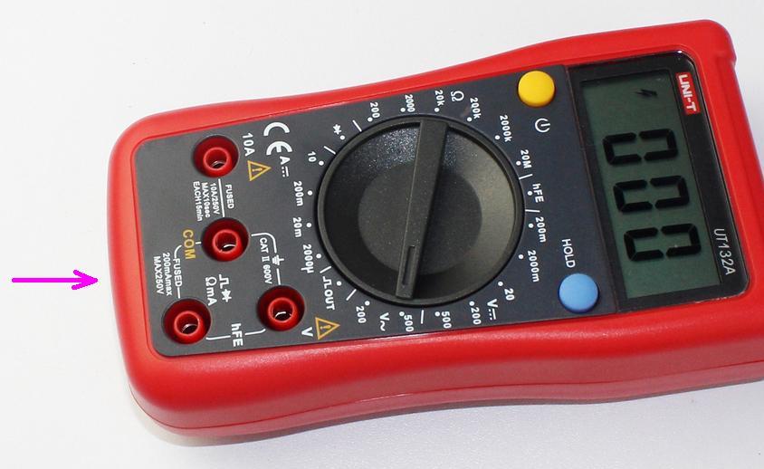
Another answerer asked what model deviceI am using. UNI-T UT132A sold by maplin, uk.

Another answerer said the multimeter should be between ground and load rather than v+ and load. I have moved it as you see in the following pic though still the bulb isn't lighting. I'll take it to maplin electronics store tomorrow and report back.

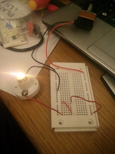
enter image description here

\$\endgroup\$
7
  • 5
    \$\begingroup\$ Is it possible your meter has a blown fuse? \$\endgroup\$
    – The Photon
    Commented Jan 24, 2016 at 0:23
  • \$\begingroup\$ @ThePhoton I can measure resistance and voltage so would that mean it hasn't blown a fuse? \$\endgroup\$
    – barlop
    Commented Jan 24, 2016 at 0:34
  • 3
    \$\begingroup\$ @barlop Current measurement channel often has got it's own separate fuse. \$\endgroup\$ Commented Jan 24, 2016 at 0:38
  • 1
    \$\begingroup\$ This one has two fuses.google.com/imgres?imgurl=https://i.ytimg.com/vi/fhiwdiHSbMM/… \$\endgroup\$
    – Passerby
    Commented Jan 24, 2016 at 0:53
  • \$\begingroup\$ And your multimeter lacks the continuity function. It would have gone on the diode feature. \$\endgroup\$
    – Passerby
    Commented Jan 24, 2016 at 0:54

3 Answers 3

5
\$\begingroup\$

Note added by barlop- It was the third one that was it. I tested it by sticking wires into the breadboard and touching the top of the wires with the probes. And then the bulb lit.

hypothesis: 1/3
You blew the fuse on the mA current measurement channel. The mA current channel is fused for 200 mA. A light bulb can sink that much (especially during inrush current), and a 9V alkaline battery can easily source that much.

UNI-T UT132A mA current rating fuse

It's possible that you have exceeded the current rating of the current measurement channel and blew the fuse inside of the multimeter. Make sure that you read the manual and know the rating. Make sure that you estimate the expected value for current before you probe it.
You can open the multimeter and examine the fuse.
You could try the other channel (the one that's marked 10A).

hypotheses: 2/3
It's possible that the positive (red) probe goes to the socket for voltage measurements. It should go to the socket for current measurement. I think in your multimeter the current measurement socket is on the left hand side (the one that says 10A).

hypothesis: 3/3
Yet another possible reason is that the probes are too thick and they don't reach the conductors in the breadboard. You can check this by setting the meter to continuity (plug probes in sockets that do continuity, of course) and probing two points on the same row of the breadboard.

\$\endgroup\$
5
  • \$\begingroup\$ It's a 9V battery(could that have been too much current?!) . I have updated the question with the multimeter model \$\endgroup\$
    – barlop
    Commented Jan 24, 2016 at 0:44
  • \$\begingroup\$ That meter lacks continuity feature. Also, you picture a slightly similar but different model than they have. UT132A vs UTM1132A. \$\endgroup\$
    – Passerby
    Commented Jan 24, 2016 at 1:17
  • 1
    \$\begingroup\$ I have accepted your answer because you got there first. It was that the metal probes were too thick to make proper contact with the breadboard. I tested it by sticking a wire into a wire into one hole and a wire into the other hole and touching the probe on the top of the wires and the bulb lit. \$\endgroup\$
    – barlop
    Commented Jan 24, 2016 at 1:24
  • \$\begingroup\$ @barlop ha. I was going to mention that earlier too. I was thinking "hmm, I wish my multimeter probe tips could fit in a breadboard like that, would be so much easier." \$\endgroup\$
    – Passerby
    Commented Jan 24, 2016 at 1:26
  • \$\begingroup\$ regarding hypothesis 2, you say current is on the left(10A).. but isn't it also the one on the bottom right(see your pic), labelled ΩmA? \$\endgroup\$
    – barlop
    Commented Jan 24, 2016 at 11:59
3
\$\begingroup\$

You have your multimeter set to the 10 Amp Current setting. To use the Ammeter in a 10 Amp setting, you have to connect the lead to the spot marked 10 Amp. It will not read or complete the circuit otherwise.

Also, your trying to measure the high side. Typically, you want to place the Ammeter on the low side. Between the Load and Ground, not V+ and Load.

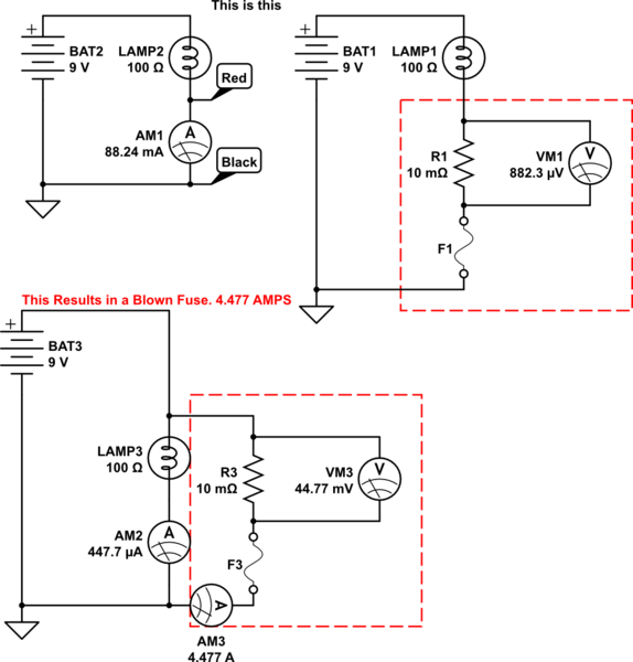
How an Ammeter works. Notice that accidentally shortening the meter across the load, IE putting it in parallel, causes 4+ Amps to go through the fuse. A 200mA (or 1 Amp as it may be) fuse will blow nearly instantly.

schematic

simulate this circuit – Schematic created using CircuitLab

\$\endgroup\$
6
  • \$\begingroup\$ I tried the dial in the other amp settings too , still 0 shown \$\endgroup\$
    – barlop
    Commented Jan 24, 2016 at 0:45
  • \$\begingroup\$ And i've moved the multimeter to between gnd and load, as you see in the new pic though still no light. \$\endgroup\$
    – barlop
    Commented Jan 24, 2016 at 0:53
  • \$\begingroup\$ @barlop You may have blown the low current fuse. Non-english video shows where it is, and how to take the meter apart. youtube.com/watch?v=fhiwdiHSbMM I've done the same thing by accidentally sticking my new meter across/in parallel with a load, in current mode. It's annoying when the fuse dies. \$\endgroup\$
    – Passerby
    Commented Jan 24, 2016 at 0:57
  • \$\begingroup\$ @barlop try moving the red lead to the 10 Amp hole, and measure again. Make sure you only put the leads in series not in parallel or that fuse will blow too. It may not read anything because the 90 milliamp or less flow, but it should light the bulb. \$\endgroup\$
    – Passerby
    Commented Jan 24, 2016 at 0:58
  • 1
    \$\begingroup\$ @barlop then there are 3 explanations. 1, both fuses have blown somehow. 2, the meter is broken. 3, the points of your leads aren't making proper contact in the breadboard. \$\endgroup\$
    – Passerby
    Commented Jan 24, 2016 at 1:14
-2
\$\begingroup\$

Also, some multimeters have a fair amount of resistance in the mA current circuit, you would have to check the resistance of the built in current shunt. The Fluke 45, an older but rather popular bench multimeter has roughly 12 ohms of resistance in the current measurement circuit.

\$\endgroup\$
3
  • \$\begingroup\$ Well, I have a 100 ohm resister that only dims the bulb it doesn't cause it to not go on at all. So resistance of the multimeter were the issue, then it'd have to be over 100 ohms resistance, which would be maybe v unlikely. \$\endgroup\$
    – barlop
    Commented Jan 24, 2016 at 0:42
  • 1
    \$\begingroup\$ 12ohms of resistance? Throw that thing out and get a new meter. That's useless for current measurement. That said, the Fluke 45 uses 0.1~0.167 Ω Shunt resistors, and the internal lead resistance of 0.003Ω, and the probe lead resistance of 0.007Ω. Both from the user and service manuals. So this is completely wrong. \$\endgroup\$
    – Passerby
    Commented Jan 24, 2016 at 1:34
  • \$\begingroup\$ @Passerby The Fluke 45 user manual (Appendix A) gives a burden voltage of 1.4V when measuring 100mA DC. If I understand that correctly, it works out to 14Ω. \$\endgroup\$ Commented Jan 11, 2017 at 5:51

Your Answer

By clicking “Post Your Answer”, you agree to our terms of service and acknowledge you have read our privacy policy.

Not the answer you're looking for? Browse other questions tagged or ask your own question.