10
\$\begingroup\$

I have what is probably a simple question. I have googled it, but the answer doesn't make sense to me.

I am learning about op-amps and creating all sorts of circuits with my nice cheap 10cent op amps. I always power these from my lab supply using +/- 5V or 15V and it works great on the solderless breadboard. Creating simple things such as simple multivibrators and so forth which would only cost a few cents.

Now I start to wonder how to power such devices from a single DC power supply, such as a 5V wall wart of which I have many lying around.

Here is what I've found.

OPTION 1:

Use a "rail splitter" such as TLE2426. But the cheapest one I can find on digikey in thru-hole form is $1.83 (qty=1). Really? More than ten times the rest of my bill of materials (1 op-amp plus a few resistors and capacitors to make a multivibrator, for instance).

OPTION 2:

Use another op-amp as shown in "Virtual Ground" section of this page: http://www.swarthmore.edu/NatSci/echeeve1/Ref/SingleSupply/SingleSupply.html

OPTION 3:

I read somewhere online that you can buy single-supply op-amps. I searched digikey but failed to find one. It has a column called "Vsupply single/dual" but all the ones I clicked on, when I went to the datasheet, the numbers quoted in that column were the dual +/- voltages.

Conclusion

Note that for small one-off circuits I don't care about paying $2 for a solution, but surely Option 2 is not the only other solution? If so, then from now on I will only buy dual-style (two-per-package) op-amps, since it seems you always need one to create the virtual ground for the other. Surely that is not the only solution?

Furthermore, Option 2 can't supply much current, I think -- does that mean it won't work in some instances? In which instances will I run in to problems with Option 2?

\$\endgroup\$
12
  • 2
    \$\begingroup\$ Practically all opamp can be run off a single ended supply. The limit of an opamp is that the output voltage must be between Vss and Vcc. You can bias your input voltage with a 2.5v dc offset and run the opamp off a single supply. Or run it with no bias and deal with the nonlinearies near the rails \$\endgroup\$
    – crasic
    Commented Jan 26, 2016 at 1:18
  • \$\begingroup\$ @crasic: "can be run" is dependent on the application, I think. For example this relaxation oscillator (falstad.com/circuit/e-relaxosc.html), there are two places where the circuit is connected to ground. If you run the op-amp off a 0V and 5V from a power supply, for instance, and then connect those two places I mentioned to the 0V of the same, it will not work. Instead, you have to connect those two places to somewhere halfway between the two voltages that power the op-amp, no? (I'm not an expert, correct me if I'm wrong. But I actually tried this on a breadboard and it failed.) \$\endgroup\$
    – dnh37
    Commented Jan 26, 2016 at 1:33
  • \$\begingroup\$ In this particular scenario a single ended opamp will not behave differently than a double ended supply opamp. In either case you need to have a middle reference voltage. You can make a poormans reference by biasing the "ground" on the inverting input to 2.5V with a resistor divider from 5V to 0V. \$\endgroup\$
    – crasic
    Commented Jan 26, 2016 at 1:41
  • \$\begingroup\$ It's worth pointing out that for applications where bipolar supplies are important (proper audio circuits, for example), one would simply design a bipolar supply onto the board (i.e. an inverting DC/DC converter for the negative rail, and maybe a linear regulator to clean things up). \$\endgroup\$
    – uint128_t
    Commented Jan 26, 2016 at 1:49
  • \$\begingroup\$ @crasic: I actually tried the resistor divider too, on the breadboard, having read that first online. I tried my two largest resistors (1MOhm), but the circuit failed and when I tested voltages at various locations in the circuit it was all weird. Then I kept reading and learned that resistor dividers do not work for such an application. Are you sure that will work? And certainly even if it somehow works for this application (say, with larger resistors) it will not work in all cases. In what cases will it fail? I'm just trying to learn here.. \$\endgroup\$
    – dnh37
    Commented Jan 26, 2016 at 1:50

4 Answers 4

11
\$\begingroup\$

The cheapest solutions, assuming you only have one supply, are to redesign the circuit so it will work from a single supply or generate the negative supply. All monolithic op-amps that I know of will actually work on a single supply- very few actually have a ground pin, so they don't know the difference between +/-5V and a single 10V supply. They do know (and don't like) signals going below the negative (or positive) supply, or even approaching it in many cases. I suggest you look at the datasheet for the LM324 which is a so-called single-supply op-amp, so-called because the output swings close to the negative supply (with a load to the negative supply) and the input common mode range includes the negative supply. There are many examples of circuits operating from single supplies in the full datasheet. A rail splitter 'chip' is used in none of them, but occasionally an extra resistor or two is required.

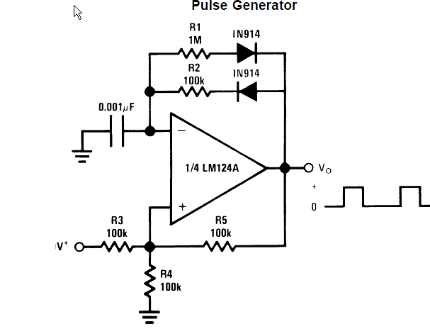
For example, as you mention a multivibrator:

enter image description here

The LM324 at a penny or two per op-amp may not be as fancy as your expensive 10-cent op-amps, but it's ubiquitous. Many of the circuits are limited by the (frankly, not spectacular) performance of that particular op-amp but you can subsitute something better if you like.

That just isn't very elegant in some cases- especially when things are DC coupled. In such cases, you can produce a negative supply with a cheap switching regulator or a charge pump chip such as a 7660. If you have a clock available, a charge pump can be made with a digital output, two MLCC caps and a dual diode.

“An engineer can do for a dollar what any fool can do for two.”

― Arthur Mellen Wellington

\$\endgroup\$
3
\$\begingroup\$

Option 4:

Use a voltage converter IC to generate a higher and a lower voltage from your 5V.

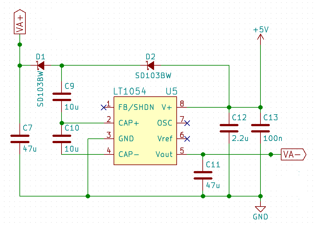
For example I use this little circuit to power OpAmps and comparators from 5V without any problems:enter image description here

This generates a voltage of approximately 9.5V at the VA+ terminal and -4.7V at the VA- terminal from just a 5V supply. If you use this to power opamps and use ground as the reference ground you'll get an asymmetric supply. Fortunately most opamps are perfectly fine with this.

The IC can be replaced with the cheaper ICL7660 or similar. Diodes can be any rectifier Schottky diode or even silicon. Just make sure it takes 100mA contiguous and about 800mA peak current.

\$\endgroup\$
4
  • \$\begingroup\$ Thanks Nils, interesting solution. However the cheapest LT1054 on digikey (qty=1) is $2.65, so this is the most expensive option. Furthermore, I don't think this always works. For example try this circuit: falstad.com/circuit/e-relaxosc.html. First look at the output, it's a 50:50 square wave. Then right-click on the op-amp and change the lower/upper voltage to something else (like change +15/-15V to +15/-5V) and look at the output. The square wave is no longer 50:50 duty cycle! The problem is, you still need that 'halfway voltage' as your ground -- halfway btwn +15 and -5 is +5V. \$\endgroup\$
    – dnh37
    Commented Jan 26, 2016 at 7:25
  • \$\begingroup\$ @dnh37 I'd argue that the price is not that important if you only need one, and you get a the ICL7660 in volume for a lot less (70 cents or so). \$\endgroup\$ Commented Jan 26, 2016 at 7:30
  • \$\begingroup\$ @dnh37 And yes, you're right that the oscillator will have different behavior, but you can work around that by redesigning the circuit. It works very well for any linear amplification jobs though. \$\endgroup\$ Commented Jan 26, 2016 at 7:31
  • \$\begingroup\$ Maxim has introduced a line that integrates the charge pump on board the same silicon as the amplifier; not sure if any of the other usual suspects have yet done that. \$\endgroup\$ Commented Mar 6, 2016 at 14:58
3
\$\begingroup\$

The simplest method, and one that I have used on occasion is a simple resistor divider. Two equal resistances (4k7 or so) in series. The divider connects across the power source, say +5 VDC. The center of the resistor divider becomes virtual ground, the point connected to +5VDC becomes +2.5VDC and the other end -2.5VDC. Depending upon the application, this is sometimes workable, however it can be prone to becoming unbalanced. Experiment with it and see if it works in your application. Adding an op-amp buffer at virtual GND can help solve potential unbalance.

\$\endgroup\$
1
  • \$\begingroup\$ Why was this downvoted? \$\endgroup\$
    – Jeff
    Commented May 10, 2019 at 21:10
3
\$\begingroup\$

There are a few other options. It's all about cost and power needs.

  1. Voltage Doubler - Inverting: It's a voltage doubler circuit, but instead of doubling the voltage, it flips the polarity. This is the option that Nils Pipenbrink shows in his answer. There are several ICs that will do this with minimal cost. Advantages: Generally cheap. Simple to use. Continuous Ground (the ground from the supply is the same ground that the circuit uses). Disadvantages: Low current capacity (it can't source much current). High frequency noise (op amps have lower PSRRs for higher frequencies).
  2. Virtual Ground - Linear Regulator Style: Two linear regulators that are biased such that they produce between them a stable, virtual, mid-rail voltage. The discussion and view of the circuit can be found here. Advantages: Higher current handling capacity (around 1.5A or more depending on actual circuit topology). Low frequency operation (it doesn't make any high frequency noise). Disadvantages: Non-continuous ground (the ground of the virtual rail is not at the same potential as the voltage source's). High part count. Not efficient (more current, more heat).
  3. Learn to design with a single supply: Not really a "fun" or "cool" solution, but there are several methods of combating DC gain in op amps. Example of the unglamorous art.
  4. Switched Power Supplies - Inverting/Transformer: There are a few switched power topologies that can be used. These range from cuk converters to SEPIC/Cuk to flybacks and full and half bridge topologies (and everything in between [places other than linear tech have solutions, I'm just most familiar with these]). Advantages: High current handling (you can actually design them to whatever current you need). Non-integer multiples and every voltage in between (they can be designed to make any output voltage you want [this ability doesn't stack with current creation, remember energy must be conserved]). Continuous ground (the ground of the input voltage can be the same as the input power's ground voltage [or it can be isolated by transformer]). Efficient. Disadvantages: Design Complexity (which also happens to go hand in hand with). High part count. Hard to test with unless you just build it. Size (these are by far the most area hogging of the solutions). High frequency content (although it's much easier to filter with these topologies, it can be problematic sometimes).

I've covered everything I could think of and that I thought of while making my bipolar power supplies from single rails. Make informed choices, do research, AND READ THE DATASHEETS (YES, THE WHOLE THING. I'VE HAD MORE PROBLEMS FROM NOT READING THESE THAN I DID FROM TIME LOST READING THEM).

\$\endgroup\$

Your Answer

By clicking “Post Your Answer”, you agree to our terms of service and acknowledge you have read our privacy policy.

Not the answer you're looking for? Browse other questions tagged or ask your own question.