1
\$\begingroup\$

Imagine I have a pulse train input which goes into a Schmitt trigger for getting sharpened. Imagine the HIGH of the input pulse train is around 8V and LOW is around zero volt.

So what should one select the lower and upper threshold voltages in this case? Does that depend on the desired HIGH output voltage? And what is the logic behind determining these threshold levels?

I found this calculator which one needs to decide about the low and high tresholds: http://www.random-science-tools.com/electronics/schmitt-trigger-calculator.htm

\$\endgroup\$

3 Answers 3

2
\$\begingroup\$

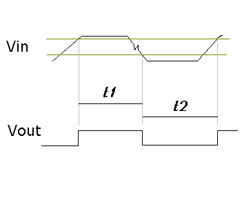
Select an upper threshold which is below the minimum high level of your signal. In other words, a level which you are certain that your input signal will exceed on each pulse. Similarly select a lower threshold above the low level of your signal. The difference between the upper and lower level is the hysteresis. The larger the hysteresis the more immune to noise your circuit will be. If this is for a production job, make sure you take account of component tolerances when choosing the threshold levels. You may also need to take into account the affect of timing skeu

enter image description here

Note that t2 > t1 due to level difference. Also note that the noise is ignored.

\$\endgroup\$
8
  • \$\begingroup\$ If minimum of the input High is 7.9V what would you choose/set for the high tredhold? \$\endgroup\$
    – user16307
    Commented Jan 26, 2016 at 12:41
  • \$\begingroup\$ If the timing issue is not a problem then we have to have a certain amount of overdrive, that is voltage beyond the threshold, in order to make sure the circuit will switch quickly. This depends on your circuit but lets say 0.2V. Then we have to take account of the tolerance in the thresholds. Lets say the accuracy of the threshold value is 10% then I would use 1.1 * Hth = (7.9 - 0.2), so Hth = 7V. \$\endgroup\$ Commented Jan 26, 2016 at 13:09
  • \$\begingroup\$ hmm but the tutorials books do not mention all these details methods. \$\endgroup\$
    – user16307
    Commented Jan 26, 2016 at 13:11
  • \$\begingroup\$ I presume that the reason you asked the question here is that you wanted to know what you need to consider then setting the thresholds. The material that you read was concerned with calculating the values to set the threshold levels. \$\endgroup\$ Commented Jan 26, 2016 at 13:13
  • \$\begingroup\$ i mean i couldnt find the way you follow in any tutorial like 1.1*Hht \$\endgroup\$
    – user16307
    Commented Jan 26, 2016 at 13:15
4
\$\begingroup\$

It's a judgement call. The first thing you want to do is look at typical input waveforms. The hysteresis offset needs to be at least the size of any temporary inversions in the signal. For example, if the main signal was a 1 kHz ±8 V sine with 20 kHz 1 Vpp sine on top of it, then you would need at least 1 V hysteresis offset to not trigger on the 20 kHz component.

The main tradeoff is that wider hysteresis offset gives you more noise immunity, but also increases the chances you wont see a real signal that is a little out of spec. Given no other information, start with the hysteresis levels at 1/3 and 2/3 of the input signal range.

You say your input is a "pulse train". If the input is really pulses, then you may not need hysteresis at all. Perhaps all you need is good gain about some convenient center point. Hysteresis is good for two things: Immunity to some noise added to a larger binary signal, and dealing with arbitrarily slow slew rates. "Pulse train" suggests you have neither problem.

\$\endgroup\$
3
  • \$\begingroup\$ do you mean using as a comparator is better? \$\endgroup\$
    – user16307
    Commented Jan 26, 2016 at 12:17
  • \$\begingroup\$ @user: Possibly. Again, it depends on your signal and what problem you are really trying to solve. A little bit of hysteresis added to what is mostly a comparator may be useful. \$\endgroup\$ Commented Jan 26, 2016 at 12:18
  • \$\begingroup\$ The incoming pulses are not sharp; they look like they are exposed to some capacitive effect. Rising edges are rising like in an RC circuit. I want to sharpen these edges. If I use comparator Im afraid of unstable output ripples might cause. If it were a comparator I would choose it middle point(reference voltage). But Schmitt triggers have two treshold levels which confuses me how to set them in this application. \$\endgroup\$
    – user16307
    Commented Jan 26, 2016 at 12:23
0
\$\begingroup\$

There is the simple, cheap, low effort approach to Schmidt trigger clean-up:

Just run it into a CD4093 (use two sections if you don't want it inverted) and don't worry about setting the level at all (beyond setting the supply voltage.) The trigger levels are not adjustable and vary with supply voltage. This works often enough and inexpensively enough that it should always be considered, though it may occasionally be discarded in favor of a more complex solution.

I default to thinking of the CD4093 as they are the Schmidt trigger logic gate in my standard stock, but any suitable Schmidt trigger logic gate could be subbed.

\$\endgroup\$

Your Answer

By clicking “Post Your Answer”, you agree to our terms of service and acknowledge you have read our privacy policy.

Not the answer you're looking for? Browse other questions tagged or ask your own question.