Several issues.
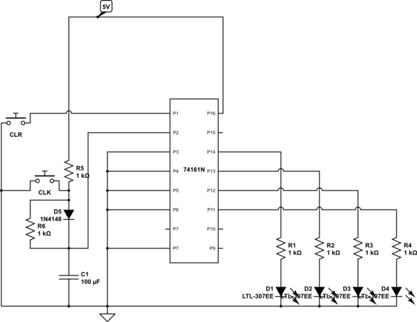
1) You claim to have copied the circuit you linked, but you didn't - you've failed to include the Schmitt trigger, typically a 7414. Without this buffering, your switch should not work on a button push, only on a release.
2) Your reset, pin 1, needs a 1k pullup from pin 1 to +5.
3) Pins 7, 9, and 10 should be tied together and pulled to +5 through another 1k resistor.
As a matter of principle, ALL unused inputs of a logic IC need to be connected to something. This is not always true of 7400 circuits, but it will be critical when you graduate to CMOS, such as 74HC chips. Get into the habit now.
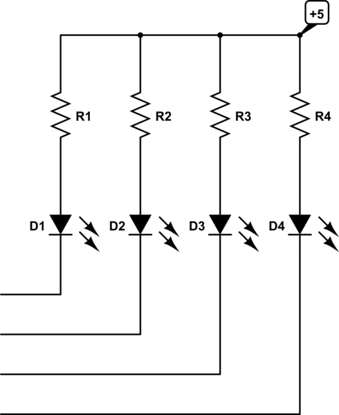
Finally, you should not count on TTL outputs driving high, as you have shown. TTL works much better pulling loads down. So your outputs should be connected like

simulate this circuit – Schematic created using CircuitLab
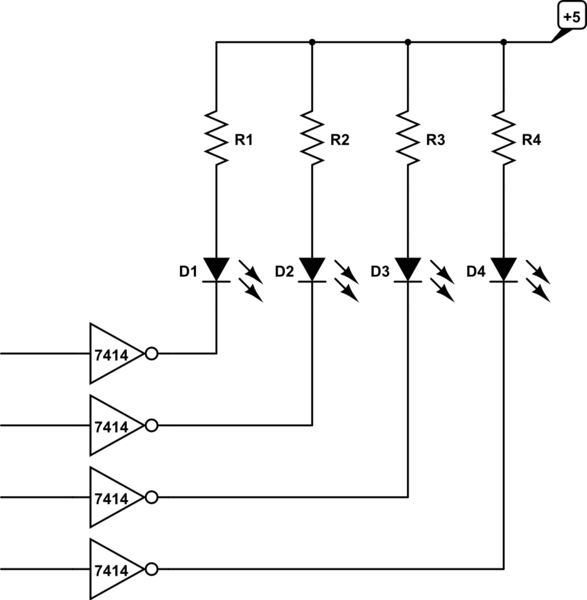
You may object that this will provide LEDs which are on when the output is low, and off when the outputs are high, which is confusing. True enough. In that case, invert the signals going to your LEDs. Since you already need one section of a 7414, and there are 6 gates per IC, you simply go

simulate this circuit


