6
\$\begingroup\$

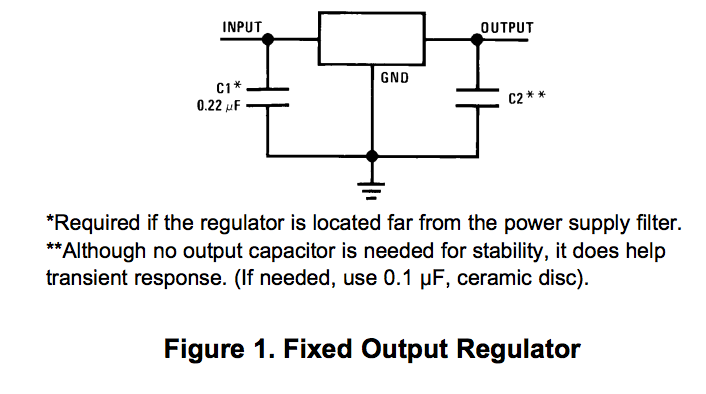
Most 7805 datasheets specify an input capacitor of 0.33uF or so. This one (the LM340 http://www.ti.com/lit/ds/symlink/lm340-n.pdf) at least specifies that the cap is only required if the regulator is "far" from the power supply filter, without further qualifying what "far" means. 0.33uF is nowhere near low impedance at power line ripple frequencies so we can rule that out.

enter image description here

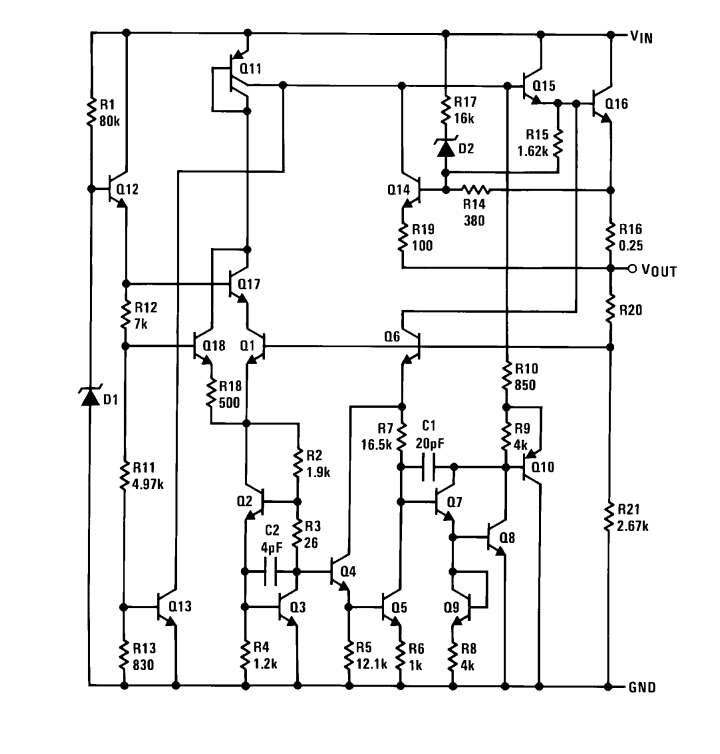
enter image description here

Edit: the differences are self evident in the title of the question.

\$\endgroup\$
2
  • \$\begingroup\$ You need a local power source to support transient current in case Input source is far away or can't support that current burst... \$\endgroup\$
    – user19579
    Commented Feb 18, 2016 at 12:59
  • \$\begingroup\$ According to this document: ti.com.cn/cn/lit/wp/snoa842/snoa842.pdf, the 7805 does not even require a capacitor, because it is compensated by the internal roll-off of the error amplifier. \$\endgroup\$
    – Bart
    Commented Mar 2, 2016 at 15:20

5 Answers 5

16
\$\begingroup\$

The input capacitor reduces the impedance of the power feed as seen by the regulator. This reduces input voltage fluctuations that occur as a function of current demand fluctuations, which the regulator has no control over. The regulator can do a better job of keeping the output steady when the input is steady.

The regulator electronics are specifically designed to keep the output steady with the input varying over a wide range (that's the point of a linear regulator), but no such circuit is perfect. Note the input regulation spec in the datasheet. That tells you how much input variations are attenuated to the output. However, that is usually at DC. As the frequency of input variations goes up, the active circuit becomes less effective at attenuating them to the output.

Fortunately, a capacitor has lower impedance at higher frequencies, thereby reducing the voltage fluctuations due to current fluctuations at higher frequencies. The capacitor does a better job as the active circuit does a worse job. Another way to think about this is that the capacitor together with whatever impedance there is in the power feed to the regulator form a low pass filter. This filter reduces the high frequency voltage fluctuations that the active circuit is less good at dealing with.

\$\endgroup\$
3
  • \$\begingroup\$ The only part I don't understand is if the input capacitor is reducing "input voltage fluctuations that occur as a function of current demand fluctuations, which the regulator has no control over" then wouldn't that capacitor be better placed on the output, or as close to the load causing the dI/dt in the first place? (thus following the usual bypass cap wisdom: small loops, low inductance, etc.). \$\endgroup\$
    – mhz
    Commented Feb 22, 2016 at 19:37
  • \$\begingroup\$ The second description, thinking of it as a filter makes more sense to me in the context of reducing line variations, but 0.022uF doesn’t start to drop significantly in impedance until the 100s of kHz. Is there some common scenario that requires filtering on the line side in those frequency ranges? \$\endgroup\$
    – mhz
    Commented Feb 22, 2016 at 19:37
  • \$\begingroup\$ @MHz: Yes, a capacitor on the output is also very useful, and is the primary means to low pass filter the current transients drawn by the load. The output capacitor is also part of the control loop, and needs to be of a certain range for the control loop to be stable. 22 nF is very small of the input cap. The impedance of the power feed goes up with frequency, due to series inductance and power supply output capacitors often being electrolytic and not good to high frequencies. In extreme cases, a regulator can oscillate if the input impedance is too high. \$\endgroup\$ Commented Mar 1, 2016 at 18:13
3
+25
\$\begingroup\$

Remember that a pcb trace or wire has parasitic resistance and inductance, these effects need to be taken into account if the regulator is farther away from the supply. These effects can be calculated with the RCL filter equations and by estimating or measuring the inductance and resistance of the wire between the supply and regulator. The source impedance is being reduced by the inductance of the wire. This is 'propped up' by placing capacitance near the 7805. Since engineers are generally lazy, we don't do this because it is much easier to put a capacitor value that is sufficiently large.

If this problem is really keeping you up and night and a few cents is going to matter in your design, then either run through the calcs and find a model for your circuit or experimentally verify it. I suppose for academics sake's you could delve into the inner workings of the 7805. A frequency model, however, could be found and you could analytically determine if it would make a difference. Which would be a colossal waste of time. A better way would be to experimentally verify it. Put the cap on, measure the AC noise across the resistor with a meter or scope. Change the value, measure again, find out which is better.

schematic

simulate this circuit – Schematic created using CircuitLab

\$\endgroup\$
2
  • \$\begingroup\$ It would be nice to know some good data about this. If anyone does the experiment, you could link to it. \$\endgroup\$
    – Oskar Skog
    Commented Apr 13, 2017 at 8:23
  • \$\begingroup\$ You can calculate resistance and inductance with a PCB trace (or wire gauge) calculator and then simulate this model in a spice simulation. Oh, and you would probably also want to throw in source impedance. \$\endgroup\$
    – Voltage Spike
    Commented Apr 13, 2017 at 15:15
1
\$\begingroup\$

A voltage regulator is essentially a combination of a voltage reference with an amplifier. Your schematic shows a fairly complex multi-stage amplifier.

The trouble with multi-stage amplifiers is you can get positive feedback through the power supply. It is extremely difficult to make a multi-stage ampflier stable if it's power supply can act as a feedback path. Therefore the incoming power needs to have a low impedance across a wide frequency range.

At the low end of the frequency range the low impedance is provided by the power supply feeding the regulator but at high frequencies the wires (or PCB traces) feeding the regulator have significant inductance and so a local capacitor is needed to maintain a low impedance.

\$\endgroup\$
0
\$\begingroup\$

The data sheet mentioned that "Bypass capacitors are recommended for optimum stability". There is a possibility that the regulator be un-stable and self oscillating. 'Far (long) connection wiring' added inductance and reduce effectiveness.

Many decades ago, when 3 pin regulator first came out, I recalled manufacturers spending more words in data sheet to explain this. Now, it seems more relax. May be the part are 'more stable' nowadays? To be on the safe side, use a low ESR capacitor as data sheet recommends.

Can a 7805 ever oscillate?

http://electronicdesign.com/boards/don-t-bypass-your-capacitor

http://forum.arduino.cc/index.php?topic=116916.0

http://www.eevblog.com/forum/projects/unstable-linear-voltage-regulator/

\$\endgroup\$
1
  • \$\begingroup\$ Low ESR? Isn't it the other around? If the ESR is too low, the circuit can become unstable (for some types of linear voltage regulators)? \$\endgroup\$ Commented Nov 27, 2019 at 2:54
-1
\$\begingroup\$

The input voltage supplies the whole regulator. If the input voltage has some high frequency components then the circuit can't operate properly because power supply rejection gets worse for higher frequencies.

Using a capacitor on the input side will limit the noise to low frequencies where the circuit can handle it.

Since the circuit contains nonlinear elements (transistors) noise on the supply can create DC shifts in the circuit, in this case the capacitor on the output does not help.

If your supply is clean, the capacitor shouldn't be required.

Another thing is transient response in case of load variations. The current consumption of the regulator depends on line/load conditions. If the supply is too far away, the line inductance will limit the ability to vary the supply current quickly. The transient performance suffers.

\$\endgroup\$

Your Answer

By clicking “Post Your Answer”, you agree to our terms of service and acknowledge you have read our privacy policy.

Not the answer you're looking for? Browse other questions tagged or ask your own question.