6
\$\begingroup\$

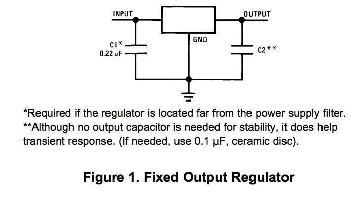
How does a cap on a regulator output improve transient response? Is this cap not more appropriately drawn next to the load where it is not being defeated by intervening trace inductance? Or does this output cap serve a different purpose than the typical bypass caps seen on a digital IC power supply pin?

http://www.ti.com/lit/ds/symlink/lm340-n.pdf

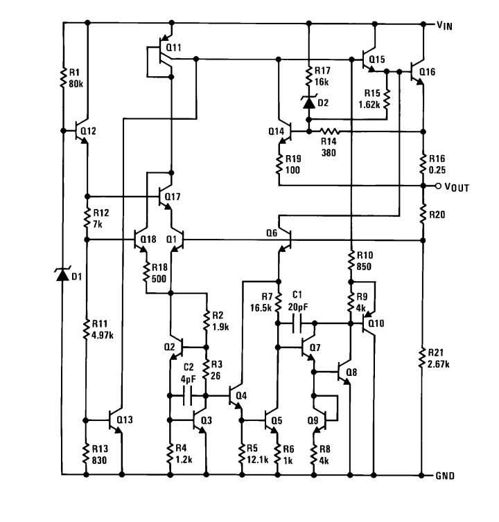
enter image description here

enter image description here

Edit: This has been flagged as a possible duplicate. While the answers may have some overlap, the titles of the three questions I asked are very specifically different questions. This should be evident upon reading the Titles.

\$\endgroup\$
7
  • 6
    \$\begingroup\$ Possible duplicate of What is the purpose of the 7805 input capacitor? \$\endgroup\$
    – Passerby
    Commented Feb 13, 2016 at 22:51
  • \$\begingroup\$ Please modify your first question if you have additional information you would like us to consider. This second question js too similar to that one to open a new thread over. \$\endgroup\$ Commented Feb 13, 2016 at 22:54
  • 2
    \$\begingroup\$ OK, so the output cap has nothing to do with the 7805 per se (e.g. compensation), but is just your usual bypass capacitor that would normally be placed at the load. This raises the question of why it would be mentioned in the application circuit at all, since the application circuit of just about any IC will also call out bypass caps on its VCC pins. If one blindly follows both application circuits, and the regulator is placed at the load, you wind up with doubled up bypass caps right next to each other. \$\endgroup\$
    – mhz
    Commented Feb 14, 2016 at 12:22
  • 1
    \$\begingroup\$ This is a good question, why are people downvoting it? \$\endgroup\$
    – endolith
    Commented Feb 16, 2016 at 5:49
  • 1
    \$\begingroup\$ endolith, that is a very good question, the user from the first comment above marked it as a duplicate to a similar but different question. different to anyone with basic reading comprehension. sadly I'm starting to see this stackexchange as less a place for learning and teaching as much as a place for hand waving and propping up ones ego. \$\endgroup\$
    – mhz
    Commented Feb 18, 2016 at 9:49

2 Answers 2

2
\$\begingroup\$

The regulator has a certain output impedance (Rout; given mostly by RE of Q16, R16 and R20). When the regulator is in regulation, this output impedance is reduced by the loop gain -- so at low frequencies (i.e. slowly changing loads), the regulator regulates well (i.e. accurately) -- VOUT is precise and doesn't change as load current changes.

However at time scales faster than the loop can respond (i.e. beyond the loop bandwidth), the output impedance is just the above expression. Thus a load current step will result in an output voltage step of deltaI*Rout until the feedback loop can 'correct' it. The capacitor at the output is in effect in parallel with this Rout, thus (at higher frequencies) keeping the effective Rout low, so load current steps don't result in load voltage steps.

\$\endgroup\$
-1
\$\begingroup\$

Such output caps are for Smoothing for very quick current droops. and ceramic caps for even much faster current noise in the regulation line such as if the sensing element is not to be perturbed by linearity loss

\$\endgroup\$

Your Answer

By clicking “Post Your Answer”, you agree to our terms of service and acknowledge you have read our privacy policy.

Not the answer you're looking for? Browse other questions tagged or ask your own question.