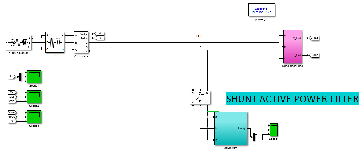
I have a demo Simulink model of a shunt active power filter using instantaneous power theory (Source, unbalanced none linear load and the filter, a very sample one, that i am using to understand the concept). Here is the model :

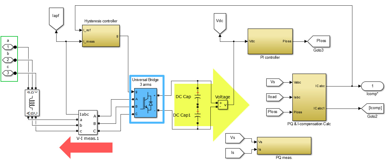
Here is a look inside the Filter :
Now, I understood that the all idea of an active filter in general is to measure the disturbance (current harmonics content), and generate the same opposite signal, and inject it in the main line, so that the injected current will cancel the harmonic signal only and leave the fundamental in the PCC.
In my model, the universal bridge (blue box) is the one generating the compensation current right (the red arrow) ? (based on the triggers of the hysteresis control block), but from what i know on the universal bridge (and power converters in general) is that they need a source of power to convert from, in our case a DC source right ? i don't see any DC source in the other side of the Bridge (Yellow arrow).
My questions :
1- am i right about my understanding ?
2- am i right about the sens of the compensation current (red arrow) ?
3- most importantly : where does the Universal bridge get its power from in order to generate the compensation current ?

