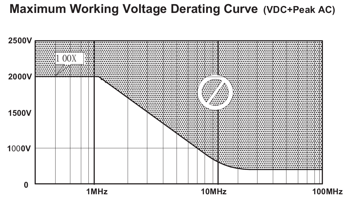
There are two types of differential probes available commercially low-voltage & high voltage. (Likes of Agilent/keysight, Tektronix, Rhode&Schwartz, Teledyne LeCroy)
The very reason for HV differential probe is also when no ground reference is available/required. Imagine two points on a 6 tap transformer. For measuring SMPS or any other frequency, go by the impedance.
While the LV probes have input impedance of the order 50K Ohm - 500L Ohm, the HV probes have input impedance of the order 2M Ohm - 10M Ohm. Depends.
There is a reason, differential probes are better than having 2 single-ended probes and doing a Ch1-Ch2 etc. Signal conditioning, scaling and offsets can be easy on a differential probe at hardware level. Than doing Ch1-Ch2 math on the scope.
Factors effecting measurement
- Vertical noise: Most oscilloscopes, even the modern DSOs have a noise floor of 20mV. This is negligible with such high voltage measurements. But if there is a significant noise to be measured, it needs a right scaling on the scope & the probe. Most DSO intelligently do auto-scale and auto-calibration functions on differential probes. Physical differential amplifier is better than software Ch1-Ch2 operation.
Yet, the source of common mode (CM) noise is not from probing path, but can be inherently due to circuitry. Transformers, switching circuits, have parasitic capacitive couplings. Also one may want to measure CM noise with a ground reference.
- Glitch or Runt measurements
For complex switching waveforms, we need a well-defines Trigger on the scope. But for the scope hardware to trigger on a glitch or a runt, we need optimal scaling without loosing accuracy of vertical measurement.
Differential probe gives, one common trigger setup.
These settings may vary with increasing frequency. A probe cable has low-pass characteristics.
- Spectral measurements
If one is doing FFTs, and things like Total Harmonic Distortion, RMS within select spectra etc. Triggers, scaling effect how Ch1-Ch2 is going to look like. Differential probe would simplify this.
the SMPS frequency should be within the limits of probe specification (Also the scope bandwidth!)
If your measurements are simple and are not nuanced, regular dual channel probing may work too

