0
\$\begingroup\$

A small alternator type 4-pole permanent magnet generator(PMG) outputs AC sinusoidal voltage from 1V to 30V where output voltage amplitude increase with frequency.

I first set the generator to rotate with a constant rpm. When I hook up the output of the PMG directly to the oscilloscope I can see the true voltage output. So far so good..

My aim is to decrease the voltage output of this PMG by a voltage divider and couple it to a comparator as an input. The reason is, if I don't do that the input to the comparator from the PMG will exceed comparator's rail voltages at high rpm.

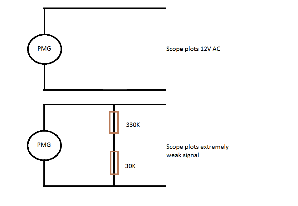
So I decided to use a 330k and a 33k resistor to make a voltage divider. I set the generator rpm such that its output was 12V when hooked up to the scope.

Then I coupled the output of the PMG to this voltage divider. I wanted to be sure if I'm doing things in the right way, so I checked the voltage across the voltage divider (across 330+30 = 360k), and what i saw was there was almost no signal in the scope. The voltage output dramatically dropped.

Here is a simple illustration about what I wrote:

enter image description here

Why does it happen? Should I use a much higher resistors values for the voltage divider?

schematic

simulate this circuit – Schematic created using CircuitLab

Figure 1 and 2. 12 V AC on open circuit. 0 V when loaded with 360k.

\$\endgroup\$
11
  • \$\begingroup\$ There's a schematic button on the editor toolbar. It's very simple to use. Add in a schematic and a photo of the setup may help too. \$\endgroup\$
    – Transistor
    Commented Feb 26, 2016 at 20:22
  • \$\begingroup\$ I added some illustration about it. Here is the PMG device: nei.co.jp/newproducts/fu_ryokuhatudenkimusenfu_sokukei.htm I just know it is a 4 pole PMG and they dont have more data sheet. And this is related to my previous question(Im trying to lower the input voltage to the comparator): electronics.stackexchange.com/questions/219421/… \$\endgroup\$
    – user16307
    Commented Feb 26, 2016 at 20:29
  • 1
    \$\begingroup\$ There really is a schematic editor button ...! You forgot to mention that your generator was the size of your thumb. Since your scope has an input impedance of 1M (confirm?) your resistors shouldn't load it too much. It sounds as though you have an incorrect value or short. Check again. \$\endgroup\$
    – Transistor
    Commented Feb 26, 2016 at 20:52
  • \$\begingroup\$ I added an editable schematic for you. Are you sure the PMG is actually connected? \$\endgroup\$
    – Transistor
    Commented Feb 26, 2016 at 20:58
  • \$\begingroup\$ Yes it was and there was a friend with me we checked several times. Im home right now. \$\endgroup\$
    – user16307
    Commented Feb 26, 2016 at 21:02

1 Answer 1

1
\$\begingroup\$

Since this turns out to be an anemometer - oh, the torture we go through to extract relevant details from the questioners! - and it's probably related to your Schmitt trigger question I suggest you try a different approach. I presume you will feed this into a micro-controller to calculate the wind speed.

If so, you could use an op-amp based precision rectifier to convert the signal to DC and use a potential divider to feed it to the micro ADC. The PMG p-p voltage should have a linear relationship with speed.

\$\endgroup\$
3
  • \$\begingroup\$ I need frequency otherwise I could measure the rms value. \$\endgroup\$
    – user16307
    Commented Feb 26, 2016 at 23:33
  • \$\begingroup\$ it wont go to a uC, it will go to a DAQ. The reason Im trying to lower the input is, it might exceed even 24V to negative input of comparator at 24V Vcc. My last option to increase the rail voltage to 36V, if I cant lower the Vin from the generator with voltage divider. I noticed if input to comparator voltage comes close or exceeds rail Vcc the pulses may produce rant pulses or they become twinlike. \$\endgroup\$
    – user16307
    Commented Feb 26, 2016 at 23:38
  • \$\begingroup\$ Just capacitively couple the output to a pulse shaper, and then measure the frequency from the output of that. Even a one or two CMOS inverters can handle the pulse shaping. Clip the input signal with some zener diodes if need be. \$\endgroup\$
    – R Drast
    Commented Feb 27, 2016 at 13:05

Your Answer

By clicking “Post Your Answer”, you agree to our terms of service and acknowledge you have read our privacy policy.

Not the answer you're looking for? Browse other questions tagged or ask your own question.