Is it possible to make PTH (Plated Thorugh Hole) at home?
Can somebody explain the procedure?
As Majenko says, a few folk have tried the conductive liquid route. From what I have read it seems to work okay but requires fine tuning and experimentation (but then so do the rest of the home brew PCB techniques if you want the best possible results)
I like the idea of conductive liquid/vacuum followed by copper electroplating to make them more reliable.
In general I agree with Mike - if you are doing this at all seriously etching your own is simply not worth it given the speed/price/ease of obtaining great quality boards. However if you need a quick hack or are in a rush to try something out though I find it certainly can come in handy to have a little etch tank sitting there.
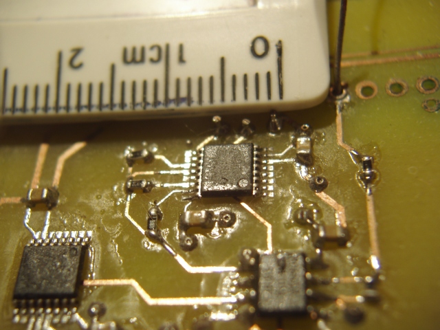
Anyway, another suggestion is to use through hole rivets. I have used these (the 0.6mm and 1.0mm ones) with great success on my etched boards. I didn't bother getting the press as it was too expensive to use for something I only do occasionally when in a hurry, but it works fine without if you can cope with a little bit sticking out on one end (~0.4mm) and having to solder them. If you are planning to do this a lot grabbing the press would probably be worth it (or hacking one together yourself with e.g. a hole punch and pin)
Here is a picture of them in use (e.g. there are 2 next to the light brown capacitors pads just below the top IC)
Resistors are 0603, traces from ~0.25mm to ~0.8mm, rivets 0.4mm hole, 0.6mm diameter.

The main problem with trying to emulate the commercial plating process is that boards are plated before etching, so you need a CNC drill. It's so cheap to get boards done commercially these days that it isn't really worth the effort.
It is possible - kind of.
See this nice blog where someone has already tried it with varying levels of success:
http://www.colinmackenzie.net/electronics/14-pcb/25-thru-hole-plating-diy-printed-circuit-boards
Basically it involves using a vacuum pump (vacuum cleaner) to suck conducting paint (like car demister repair paint) through the holes to plate them.
For my first attempt, after etching both sides of the pcb, but before drilling, I placed a large sticky label over the pcb (mine were transparent like scotch tape). I then setup my cnc machine and drilled all the holes. Using the conductive liquid from the defroster repair kit and an old glossy business card I squeegeed the liquid across the PCB over all the drill holes. I then used a vacuum on the pcb bottom side to suck the liquid through the holes.
For my second attempt I built a vacuum table out of a 4$ cutting board. With my CNC machine I milled a graph pattern deep (75%) into the board. This allowed the PCB to sit on any part of the cut-out and still have lots of air circulate underneath. The graph cut-out was about 4x5 inches, I would tape over any part of the vacuum table not covered by the PCB to get a good seal so air would only be sucked through the holes in the PCB.
He has had some mixed results though:
I've had a problem with the Silver conductive fluid recently. I used a few vias to tie the ground of my regulator to the ground plane on the bottom of the PCB. In operation, this regulator's ground pin had a tendancy to float on occasion. Perhaps it had to do with current output, I am not sure. The resistance of these vias would intermittently change upwards to 50ohms! Perhaps this plating is sufficient for small signal traces, but I am hesitent to depend on them on vias for power distribution.
One comment on the site has a possible solution to the problem though:
Why don't you try copper-plating the through holes after you've activated them with your silver ink? Doing this will result in much more robust and reliable vias, and it's not all that complicated to do. This site gives a good overview of the process:
If anyone still has interest, this video shows how to plating through hole at home using pyrolysis of copper hypophosphite to activate the holes.
Look this: http://youtu.be/fY0AjzKLA-8
The other answers are very good and they are the standard way (or so I've heard) for the hobbyist to do plated through hole at home.
Another way, though, that I've recently seen uses a type of silver or solder paste that has a higher melting point than the standard solder paste. The idea is to mask the top layer with some type of removable sheet, drill the holes through the sheet and your PCB, coat the top layer with the silver paste, suck it through using a vacuum table, then bake it. After removing the film, you now have a PCB with plated through hole.
Here is LPKF's page on it and a video demonstration of it.
Please note that I don't work for LPKF and I've never actually used this myself, I've only seen it online.
To me, the real genius is using a paste with a higher melting point than that of the solder paste. This makes it immune to the reflow step that will happen after the plating is done. I would be very interested in knowing a formula for making this paste yourself, or, at the very least, a cheap and readily available source for the paste so that the average hobbyist could do this themselves.