2
\$\begingroup\$

I am trying to use a BCD to 7 segment decoder to power my 7 segment display. This is the decoder I'm using (http://www.mouser.com/ProductDetail/Texas-Instruments/SN74LS47N/?qs=sGAEpiMZZMtYFXwiBRPs05jHvQJpC1NM).

Right now, I just have it hard wired to feed ground into it's binary inputs. I believe this should result in a zero being displayed. However, nothing is being displayed. I used a multimeter to check the outputs and found that only around .14 volts were being supplied out of the chip. I have verified that the supply voltage supplied to the chip is 5 volts and the chip ground is correct. I tried swapping the chip, and that didn't help. If I directly wire the 7 segment display, it operates normally.

When I change the inputs, I find that the correct outputs are high and low, but the high only goes to .14 volts.

Did I wire something wrong? Or maybe I misunderstood the operation of the chip? I admit I'm a novice when it comes to this stuff.

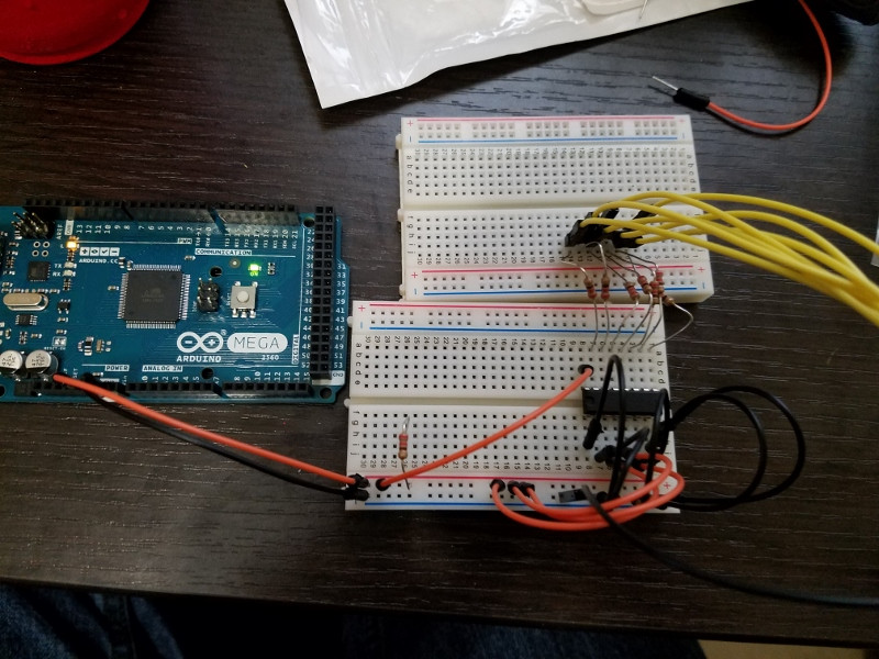
Breadboard Setup

\$\endgroup\$
10
  • 1
    \$\begingroup\$ You will appreciate that it will be impossible for us you figure out your circuit from the photo. There is a schematic editor built-in to the question / answer editor toolbar. Sketch out the relevant parts of your circuit and you'll get much more help. We all love schematics here. \$\endgroup\$
    – Transistor
    Commented Mar 18, 2016 at 20:56
  • \$\begingroup\$ Sorry. I'll work on adding a schematic. \$\endgroup\$
    – Ryan
    Commented Mar 18, 2016 at 21:01
  • 2
    \$\begingroup\$ 7447 has open collector outputs. Step 1 : read up on open collector outputs. Step 2 : pull the outputs to +v via a resistor and your LED. \$\endgroup\$
    – user16324
    Commented Mar 18, 2016 at 21:01
  • \$\begingroup\$ Along with what @BrianDrummond said, if your 7-segment display has a common anode pin, I think it should be sufficient to just tie this to V+ via a resistor. \$\endgroup\$ Commented Mar 18, 2016 at 21:11
  • \$\begingroup\$ @DigitalNinja I'm using common cathode (amazon.com/gp/product/B00EZBGA4U?ref_=pe_1196280_123950170) \$\endgroup\$
    – Ryan
    Commented Mar 18, 2016 at 21:20

2 Answers 2

2
\$\begingroup\$

The chip you are using has open collector outputs. You won't measure any voltage on the output of the pins as this are used to sink not source.

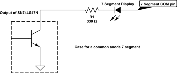
If you think of the segments of your 7 segment display of LEDs, the output of your chip will actually function as the ground. If we were to look at the internal of your chip then it would look like this

schematic

simulate this circuit – Schematic created using CircuitLab

When your output is 'high' it turns the transistor on and allows current to flow from the COM pin of the 7 segment display, through the LED and to ground. This however is only the case for a common anode 7 segment display. If you have a common cathode 7 segment display then your LEDs are going to facing the opposite direction which means when the transistor turns on your will have both the anode and cathode of the LED connected to ground, hence why you won't see the LED turn on.

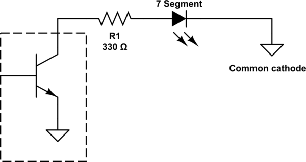
Edit: After reading that you've used a common cathode 7 segment display then this is what your circuit actually looks like

schematic

simulate this circuit

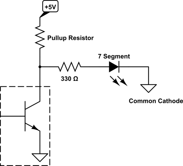
All you've got here is a bunch of grounds so there's not going to be any current flowing through the LEDs of your 7 segment display. In response to the comments of the guys above, what they're suggesting is to add some pull up resistors to the output. What this means is that when the output is low and the transistor is off, the LEDs will be powered by the 5V that flows through the pull up resistor

schematic

simulate this circuit

The easiest way however is to just buy a common anode 7 segment display

\$\endgroup\$
6
  • \$\begingroup\$ Thanks, that really helps. I have a common cathode display. Does this mean this chip won't work? Right now, the output is inverted (as in for every number the parts that should be lit aren't, and the parts that shouldn't are). Edit: Looking at other responses, it does. Oh well. Time for new chips. \$\endgroup\$
    – Ryan
    Commented Mar 18, 2016 at 21:26
  • \$\begingroup\$ You can use pull up resistors on the outputs, but that's an extra resistor you have to add to each output and depending on the size of the pullup resistor will limit too much current and make your 7 segment display dull. If you do buy a new chip don't go for the SN74LS48 as although it has a high output it can only source around 2mA and you won't be able to use it to drive your 7 segment display directly. Personally I'd buy a common anode 7 segment display, that way you don't need to change your current circuit \$\endgroup\$
    – user103993
    Commented Mar 18, 2016 at 21:37
  • \$\begingroup\$ Thanks again. Instead of buying a new display, could I just buy a different chip? Also, would you mind giving me a hint on how to identify if the chip operates a cathode or anode display? When I look at the datasheet for the SN74LS47N, I can't find where it describes what kind of display it operates (anode or cathode). I'm sure I'm missing something obvious, I just don't want to make the same mistake twice. \$\endgroup\$
    – Ryan
    Commented Mar 18, 2016 at 21:41
  • \$\begingroup\$ Right now, this circuit is just a prototype to make sure I understand the components (and to identify problems like these), so changing the circuit doesn't really matter too much to me right now. The reason I like my current displays is because I've already created prototypes assuming their exact dimensions (as I'm doing something a bit odd with these where their physical dimensions are very important. \$\endgroup\$
    – Ryan
    Commented Mar 18, 2016 at 21:41
  • \$\begingroup\$ If you're looking for a direct chip replacement as opposed to replacing the 7 segment display then try the MC14511, you might need to use different resistors on the outputs of the chip but it will do what you're after \$\endgroup\$
    – user103993
    Commented Mar 18, 2016 at 21:42
0
\$\begingroup\$

You have almost certainly misunderstood your display and how it works. It's impossible to tell for sure, since you have not identified your display or provided a data sheet.

Nonetheless, I notice that your picture shows 7 yellow leads and a black lead connecting to the display which is outside of the picture. The black lead is clearly connected to the circuit ground, and presumably connects to the display common.

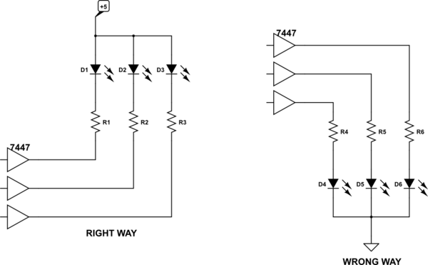
Now, there are two different types of 7-segment displays, common cathode and common anode. A 7447 requires a common anode display. The difference between the two is

schematic

simulate this circuit – Schematic created using CircuitLab A 7447-type driver MUST be used with a common anode display, and connected like

schematic

simulate this circuit

If you accept that current flows from + to minus, a 7447 can sink current, but cannot source it. That is, LED current can flow into the 7447, but not (to any usable degree) out of it.

\$\endgroup\$

Your Answer

By clicking “Post Your Answer”, you agree to our terms of service and acknowledge you have read our privacy policy.

Not the answer you're looking for? Browse other questions tagged or ask your own question.