4
\$\begingroup\$

I am trying to connect three 7-segment displays to show the result. I thought about using the IC 7448 (I could also use the 7447), but I assigned 4 outputs to each encoder (first issue, as I need 3 displays since the maximum obtainable number is 225) and connected each decoder output to its respective segment on the display. The second issue is that when going past the number '9,' the results on both displays are incorrect, as they don’t even form numbers (probably due to overflow; I’m not sure—I’m not an engineer). Could you provide any suggestions or recommendations for making the correct connections to achieve my goal? I can use the integrated circuits available in Quartus II software.

I CAN ONLY MODIFY THE CIRCUIT STARTING FROM THE OUTPUT OF THE MUTIPLIER

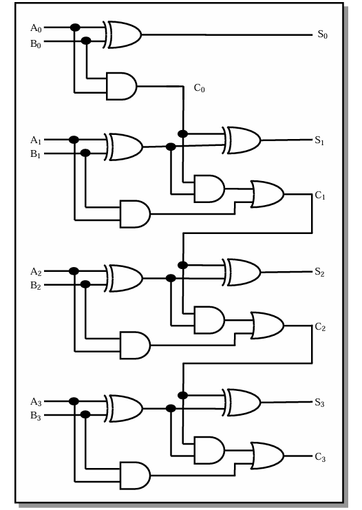
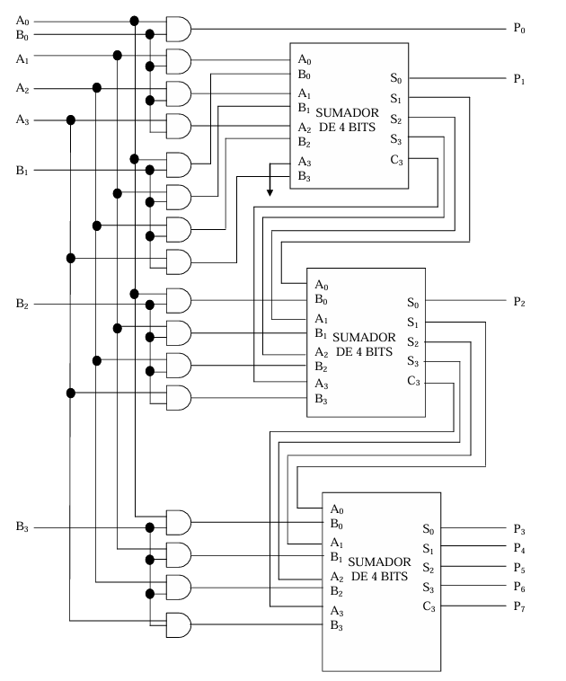
**This is the logic circuit I built in Quartus; the block labeled 'sumador de 4 bits' (IMAGE 2) is a 4 bit adder, "c" I believe corresponds to the "carries" and "s" corresponds to the outputs.

enter image description here**

**This is the logic circuit of the block shown in the multiplier.

**

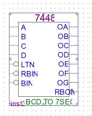
These are the inputs and outputs of the 7448; I am not familiar with the functions of the special gates.

enter image description here

\$\endgroup\$
5
  • \$\begingroup\$ You need to convert the 8-bit binary signals to three Binary Coded Decimal digits before you can use the 7448. This is not trivial. Are you allowed to use synthesis tools? You could brute-force it by synthesizing a lookup table. Or, if you are good at math, you could describe the Binary to BCD function, and then synthesize it. \$\endgroup\$
    – Mattman944
    Commented Oct 31 at 14:29
  • \$\begingroup\$ (There are just four products greater than 192: 195, 196, 210, and 225.) \$\endgroup\$
    – greybeard
    Commented Oct 31 at 18:17
  • \$\begingroup\$ I recommend not to try to think up a solution in terms of 1960ies MSI when it doesn't come natural/spontaneously to you. \$\endgroup\$
    – greybeard
    Commented Nov 1 at 10:58
  • \$\begingroup\$ You created 4-bit adders for your project. You also have access to gates. You have what you need to make a binary-to-BCD converter. \$\endgroup\$ Commented Nov 2 at 4:12
  • \$\begingroup\$ I CAN ONLY MODIFY THE CIRCUIT STARTING FROM THE [product P] are you allowed to use signals A and B, or just P? \$\endgroup\$
    – greybeard
    Commented Nov 2 at 7:56

3 Answers 3

6
\$\begingroup\$

The 7447 and 7448 are BCD-to-seven-segment display drivers. They are not fully decoded (saving transistors was important in the ~1960s), so invalid inputs provide oddball outputs rather than blanking or showing some semblance of a hex character. Valid BCD inputs are 0x00 .. 0x09, and 0x0A to 0x0F are invalid. From this datasheet:

enter image description here

The display for each input code is unique (assuming zero blanking is not used) so you can actually read the binary number directly, although it's not very user-friendly until you memorize the top 6 symbols including blank. But I doubt that's the point of the exercise.

If you intend to show the result in hex format you would need to make or find a HEX-to-seven-segment display driver or decoder. If you intend to show the result in decimal digits (from 0 to 225 in this case) you would need to interpose a logic circuit between the multiplier output and the BCD display drivers to convert 8 bit binary to 3 digit BCD. I suspect the object of your assignment is the latter.

One such method is the 'add 6' algorithm.

\$\endgroup\$
3
  • \$\begingroup\$ I believe that the "oddball outputs" for 0xA - 0xF inputs will be shown on the 7447 and 7448 datasheets. \$\endgroup\$ Commented Oct 31 at 16:04
  • \$\begingroup\$ @PeterBennett Indeed they are (not all datasheets show the display though). Added the relevant section to the answer. (Somewhat) later designs such as the 4511 blank on invalid inputs. And the MC14495 and, if memory serves, some others decode hex so they could be used for either BCD or hex. \$\endgroup\$ Commented Oct 31 at 16:22
  • 2
    \$\begingroup\$ That's a classic textbook example of optimizing with don't cares. \$\endgroup\$
    – user71659
    Commented Nov 1 at 5:50
3
\$\begingroup\$

If you're building this in Quartus, you can create a lookup table for 4-bit binary to 7-segment display. Then use two of them for your two product digits.

Here's some Verilog code to do that: https://christophervickery.com/babbage/courses/cs343/Using_hex2sevenseg.xhtml

Want decimal? You'll need to convert your 8-bit product to BCD, then drive your displays. Here's how to do that in Verilog: https://verilogcodes.blogspot.com/2015/10/verilog-code-for-8-bit-binary-to-bcd.html.

This answer shows a VHDL approach to binary-to-BCD. But if you need to render it as gates, there's a block diagram. https://stackoverflow.com/questions/23871792/convert-8bit-binary-number-to-bcd-in-vhdl

You'll of course need three BCD display digits since your max product is 15 x 15 = 225. If you also restrict your inputs to be BCD, then you only need two output digits, since your max product is 9 x 9 = 81. In any event you could use the 7447/7448 for the display, in trade for doing the legwork to convert the product to BCD.

Another option is to make your multiplier native BCD. There's plenty of references for that.

\$\endgroup\$
2
\$\begingroup\$

You can do this in various ways, none of them pretty.

  1. You can use 3 7447s, looking at 3 lsbs, 3 midbs, and 2 msbs, with the output being in octal. As a real stretch you could claim that this was useful training for dealing with IP addresses.
  2. If you can find them (and I doubt you can at any reasonable price) you could go with 3 74185s https://susta.cz/fel/74/pdf/DM74184_74185.pdf to convert 8 bit binary to 2 1/2 digit BCD. Page 7 of the data sheet shows the circuit.
  3. You could use a less exotic chip like the 74169 (binary up/down counter) and a the 74160 or 74162 decade counter. At regular intervals, load your product into an 8-bit binary down counter, then count down and stop at zero (it only takes a single inverter to invert the carry out and feed it back to the enable input). At the same time you are counting down, set a 3-digit binary counter to zero, then count up in synchrony with the down counter. When the down counter stops, latch the decade counter outputs and then use 7447s to drive 3 7 segment displays.
  4. Get hold of two HP 5082-7340 hex displays and connect them directly to the multiplier outputs. Again, price is likely an issue.
  5. Get something like an Arduino hobbyist board with at least 10 output lines and do the counting and BCD conversion in software. If you can get something with 21 outputs you can also do the segment decoding in software as well.
\$\endgroup\$

Your Answer

By clicking “Post Your Answer”, you agree to our terms of service and acknowledge you have read our privacy policy.

Not the answer you're looking for? Browse other questions tagged or ask your own question.