0
\$\begingroup\$

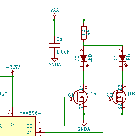
I have designed a simple circuit to drive LEDs using a MAX6964 I2C LED driver/GPO chip. Unfortunately, I somehow missed missed that the outputs are open-drain current-sinking outputs. This is not working because my circuit uses an N-channel mosfet in a low side configuration. From my research on this site, I found a few articles on N-channel and P-channel mosfets but none seem to address my specific question.

From my readings on this site, the N-channel gate needs a positive voltage to switch it. Again, unfortunately the output of my Max6964 is a current sink not a current source. I have already made some pc boards with the design that includes surface mount parts. I am trying to "salvage" these pcbs with the smallest possible change of components and/or trace cutting & rewiring. Here are my thoughts:

  1. Simply replace the the N-channel mosfet with a P-channel mosfet. Is that correct? My hunch is this will not work.

  2. Leave in the N-channel mosfet and add a pull up resistor (value?) between the gate and the supply (VAA) work? This would invert the logic for turn on the LED but I can live with that.

  3. Since the Max6964 can sink 50mA on each port, remove the N-channel mosfet, jumper the gates to the sources, and increase the value of resistor R6 to some higher value (~100 ohms) to limit the current. I am trying to maximize the intensity of the LEDs so I am not sure this option is the best.

Here is my circuit: LED driver circuit snippet

Here is the simplified Max6964 output port from the data sheet:

[![Max6964 simplified output port][2]][2]

Thanks a bunch in advance for any feedback!

[IMPORTANT EDIT] VAA is +5V PWM signal. So although I liked the pull up idea, I don't think it will work.

[EDIT 2016-04-20 proposed:]

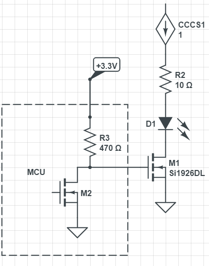
enter image description here

\$\endgroup\$
9
  • \$\begingroup\$ Why not just connect the gate pad to the drain pad and omit the MOSFET entirely? \$\endgroup\$ Commented Apr 20, 2016 at 19:26
  • \$\begingroup\$ What LEDs (part number) do you use in your design? How many LEDs do you want to connect to one output? \$\endgroup\$
    – Master
    Commented Apr 20, 2016 at 19:38
  • \$\begingroup\$ And, by the way, you have to use separate "R6" resistors: one resistor for each LED. \$\endgroup\$
    – Master
    Commented Apr 20, 2016 at 19:39
  • \$\begingroup\$ @Master1, 1 LED per output and can draw up to 100mA ea. A working circuit that I started with was a 74HC4514 driving the base of the N-Channel mosfet. Why would I now need separate resistor per LED? Note, that both LED will never be turned on at the same time. \$\endgroup\$ Commented Apr 20, 2016 at 21:31
  • \$\begingroup\$ Then I suggest: removing MOSFETs, using 2 outputs of MAX6964 in parallel for each LED. You can safely drive about 80-90 mA in each LED by this design. Of course, you need spare outputs. \$\endgroup\$
    – Master
    Commented Apr 20, 2016 at 21:52

4 Answers 4

3
\$\begingroup\$

Go with the pullup, if you want to keep your MOSFET driver.

Make sure you don’t sink too much current into the pin by checking that $$V_{aa}/R < 50\text{ mA}.$$

If you don’t need super fast switching, a resistor in the order of a few kOhm (such as 4.7k) will do fine.

\$\endgroup\$
2
\$\begingroup\$

1. Use a P-channel mosfet. You have the opposite problem with this, you need a pull-up to turn off the mosfet. Also, depending on the voltage of VAA this may not work even with a pull-up.

2. Add a pull-up from Gate to VAA. This would be my choice. Since the MAX6964 uses PWM you will need a value of around 4k7 to rapidly charge the gate capacitance..

3. Bypass the mosfet. This will limit your options on the amount of current you can drive through the LED.

\$\endgroup\$
3
  • \$\begingroup\$ Thanks everyone for fast response times :-) One important detail I omitted. I just edited it but to reiterate: VAA is a +5V PWM signal so I don't think the pull up will work. \$\endgroup\$ Commented Apr 20, 2016 at 19:45
  • \$\begingroup\$ @JoeChiphead the MAX6964 also has PWM outputs, so why have another PWM for VAA? Are the PWM's synchronized at all? If they are then the pull-up may still work. If they are not sync'd then this circuit would never work. \$\endgroup\$
    – Steve G
    Commented Apr 20, 2016 at 20:21
  • \$\begingroup\$ Considering that VAA is a different voltage, would adding a pull up between the gate and the +3.3V work? Thanks! \$\endgroup\$ Commented Apr 20, 2016 at 22:57
1
\$\begingroup\$

Since the '6964 can already do current control just tie the drain pad to the gate pad, omit the MOSFET entirely, and fix it in software.

\$\endgroup\$
1
  • \$\begingroup\$ Thanks. In my design, VAA varies according to a sine wave. Although the '6964 has PWM control, to take advantage of this I would have to continuously transmit a changing PWM pattern that simulates the sine wave. Doing so over I2C bus would limit the sinusoidal frequency. Supplying the LEDs with a separate sinusoidal current source (VAA) allows a higher frequency range. \$\endgroup\$ Commented Apr 20, 2016 at 20:20
0
\$\begingroup\$

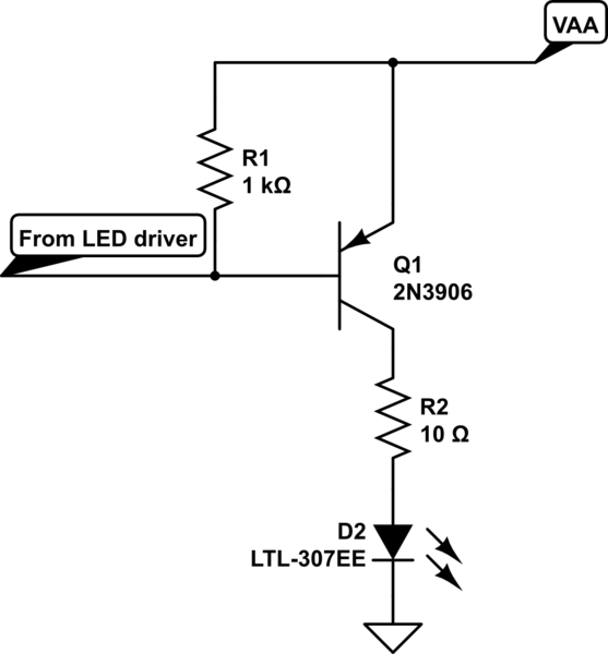
schematic

simulate this circuit – Schematic created using CircuitLab

The P/N of BJT and LED in schematics have no meaning. You should use your LED. As for BJT, it must reliably handle 100 mA load current (very easy), have transient frequency above 300 MHz for fast switching (easy) and preferably have low VCEsat (saturation voltage between Collector and Emitter).

You must put a resistor between MAX6964 output and Node "From LED driver". It must provide about 3-5 mA current at your minimum VAA-1V. For example: VAA = 5V, then the resistor is 1 kOhm.

\$\endgroup\$
4
  • \$\begingroup\$ this is excellent. Could I still use this circuit if VAA was an externally controlled current source varying between ~=5ma to 100ma ( V ~=1.5V to 1.9V)? \$\endgroup\$ Commented Apr 22, 2016 at 18:34
  • \$\begingroup\$ Sorry for a late reply. Yes, you can, however, the problem is: varying current from VAA definitely changes the voltage at VAA node. This makes a current through R1 uncertain. If VAA is a true current source with high output impedance: I suggest reduction of R2 to few Ohms (may be, no R2 at all). Then VAA voltage is almost direct voltage drop over the LED D2. It depends on VAA current a little. Then VAA is 1.8 - 3.2 depending on the LED type. You can set R1 according to the minimal voltage, for example, to 330 Ohms. \$\endgroup\$
    – Master
    Commented Apr 26, 2016 at 12:10
  • \$\begingroup\$ Thanks. I understand. What if the pullup tied to the +3.3V and not to VAA? MAX6964 can sink 50mA. I've drawn it, but Forum comment doesn't seem to allow pasting new image... \$\endgroup\$ Commented Apr 28, 2016 at 14:29
  • \$\begingroup\$ See new image edited into original post above labeled [EDIT 2016-04-20 proposed:] \$\endgroup\$ Commented Apr 28, 2016 at 14:36

Your Answer

By clicking “Post Your Answer”, you agree to our terms of service and acknowledge you have read our privacy policy.

Not the answer you're looking for? Browse other questions tagged or ask your own question.