2
\$\begingroup\$

I want to make a little battery-powered portable phone charger (maybe 9V).

I have seen similar USB powered battery chargers such as the Mintyboost.

My phone is the HTC Hero. Would the design be basically be the same? Except instead of USB I'd use a mini-USB perhaps? I believe the charger is a standard mini-USB.

\$\endgroup\$
4
  • 3
    \$\begingroup\$ What is wrong with using mintyboost as is? \$\endgroup\$
    – Kellenjb
    Commented Dec 8, 2011 at 16:06
  • \$\begingroup\$ If you're using a 9V battery, you'll want a switching regulator. (Not an LM317) \$\endgroup\$
    – user606723
    Commented Dec 8, 2011 at 16:37
  • \$\begingroup\$ Well the mintyboost is USB, i would need a miniUSB.....I assume the circuits are still the same? \$\endgroup\$
    – user3073
    Commented Dec 9, 2011 at 0:23
  • 3
    \$\begingroup\$ @Sauron: The difference between miniUSB and USB is only the connector. If you have a look at the USB cable that came with your phone, you will (most certainly) find that it pefectly fits into a regular USB port, your wall charger or the mintyboost. \$\endgroup\$
    – 0x6d64
    Commented Dec 9, 2011 at 11:33

3 Answers 3

2
\$\begingroup\$

Reducing linear regulator dissipation when a USB supply is provided from a higher voltage source:

In Majenko's LM317 supply which is operated from 12V, you can more than halve the power dissipation in the LM317 under wort case conditions by adding a cheap air cooled wire mounted series input resistor.

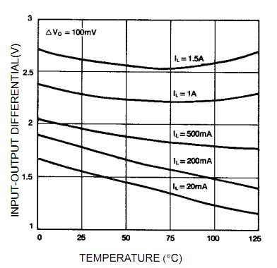
The LM317 needs 2 to 2.5V headroom at lower currents or say 2.75V under extreme load and temperature conditions. (See Fig 3 in the datasheet, - copied below).

LM317 headroom or dropout voltage
enter image description here

Rin has to be sized such that it does not drop excessive voltage when V_12V is at its. minimum, Vdropout is worst case for the conditions and the series diode drop and output voltage are allowed for.

Voltage across resistor must always be less than =

  • Minimum Vin

  • less Maximum Vdiode drop

  • less Worst case dropout relevant to situation

  • less output voltage

So Rin <= (v_12 - Vd - 2.75 - 5)/Imax.

For 12V minimum Vin, and say 0.8V diode drop and say 1 amp out that's
(12-0.8-2.75-5)/1
= 3.45/1
= 3R45
= say 3R3.

Power in R = I^2R = 3.3W so a 5W part would be marginally acceptable and 10W would be better.

Dissipation in the LM317 falls from > 6 Watt to < 3 Watt.

An excellent example of a suitable wire lead mounted aircooled resistor would be a member of this nicely specified Yageo family of wirewound resistors with members rated from 2W to 40W air cooled. A 10 Watt units is in stock at Digikey at $US0.63/1.


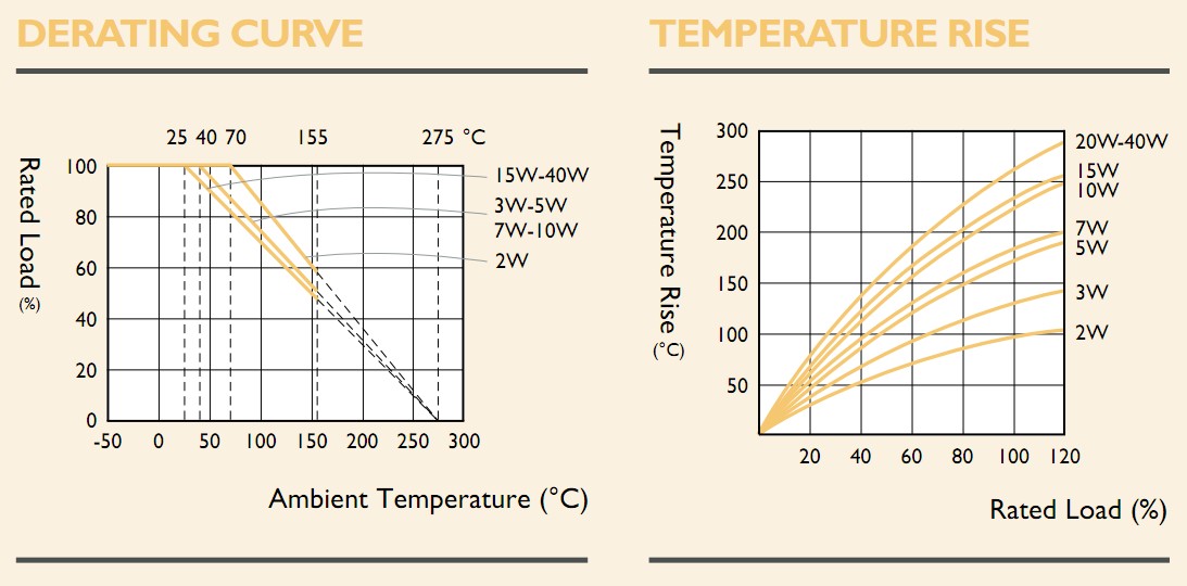
Resistor ambient temperature ratings and temperature rise:

Nice to have are these two graphs from the datasheet above which allow real world results to be estimated.

The left hand graph shows that a 10 Watt resistor operated at 3W3 = 33% of its rate Wattage has an allowable ambient temperature of upto 150 C (actually about 180C if you plot the operating point in the graph but the manufacturer says 150 C max is allowed.

The second graph shows that temperature rise for a 10W resistor operated at 3W3 will be about 100C above ambient. A 5W resistor from the same family would be operating at 66% of rating and have a temperature rise of 140C above ambient. (A 40W would have about 75C rise but 2 x 10W = under 50C and 10 x 2W only about 25C !!!.

The decreasing temperature rise with an increasing number of resistors with the same combined Wattage rating in each case is presumably related to "Square cubed law" action as there is less cooling surface area per volume as size increases.
enter image description here

http://www.yageo.com/documents/recent/Leaded-R_SQP-NSP_2011.pdf

\$\endgroup\$
3
\$\begingroup\$

The design can be identical to the Mintyboost, as it's compatibility list includes the HTC Hero (GSM). Since the Mintyboost can provide up to (at least) 500mA at 5V, the maximum a regular USB 2.0 port is supposed to spit out, any device that fits under the USB 2.0 power spec* can be powered by the Mintyboost. The HTC Hero USB port is designed for HTC's proprietary ExtUSB[WP link] plug, which is backwards-compatible with mini-USB/mini-B, so you can use a standard-A-to-mini-B cable.

I recommend a battery other than the 9V (PP3) to improve all of power, space and cost efficiency. The Mintyboost uses AA's -- they'd be spiffy.

*Not the USB 2.0 power port spec, though, which can provide more than 500mA if so rated.

\$\endgroup\$
2
\$\begingroup\$

The easy option:

Just use any portable USB charger (I have a solar powered one that is very useful) with a standard USB A connector, and use the cable that came with your phone. That way you can use it to charge/power any USB device.

The harder option:

Make your own.

Again, I would seriously suggest using a USB A connector instead of the micro one that is on the phone.

There are two types of charger - slow and fast.

The slow ones only supply 100mA of current, and are also the simplest. It's just a straight +5V/GND on the USB's power/ground connections. You can create that any way you like - a simple linear regulator is probably easiest.

Fast chargers can supply 500mA, and require a little extra circuitry to tell the phone that they are capable of giving the extra current.

Here is a little circuit I designed for a small project of mine - a simple fast charger that can charge 2 USB devices at once off a car battery:

Simple linear regulated fast charger

(Full article here)

The two voltage dividers are what tell the phone to use the extra current.

The regulator can get rather hot though, and I am shortly going to embark on re-designing it as a switching buck power supply instead.

A half-way option:

For simplicity, you could just get an existing car cigarette lighter style USB charger adapter and rip the circuit out of there. You will find that it is a simple buck regulator. Just hard wire that to your battery source (it should run fine off 9v) and bob's your uncle.

By the way - I use the above circuit to charge my HTC Wildfire nice and fast.

\$\endgroup\$
6
  • \$\begingroup\$ Holy cow! What do you use on that regulator to keep it from desoldering itself? \$\endgroup\$
    – Mark
    Commented Dec 8, 2011 at 21:43
  • \$\begingroup\$ At the moment, a heatsink and fan from an old video card. It works quite well. I have some switching chips arriving from Maxim soon to experiment with. I'll be posting the results (and schematics) on my site when I have something working. \$\endgroup\$
    – Majenko
    Commented Dec 8, 2011 at 21:53
  • \$\begingroup\$ @Majenko - First, don't most phones support a "super-fast-charging" mode over 500mA these days when using a wall wart or car charger? \$\endgroup\$ Commented Dec 9, 2011 at 22:09
  • \$\begingroup\$ Wall-warts etc implement the voltage divider as depicted in the schematic. What they don't often provide is two sockets, nor the fun of building your own. \$\endgroup\$
    – Majenko
    Commented Dec 10, 2011 at 0:03
  • \$\begingroup\$ @Majenko - Right, and both the wall wart -> USB chargers and your implementation don't limit the current. I'm objecting to the line Fast chargers can supply 500mA - With circuits like this, the current draw is completely up to the phone, and many phones draw a good deal more than 500mA. \$\endgroup\$ Commented Dec 10, 2011 at 0:20

Your Answer

By clicking “Post Your Answer”, you agree to our terms of service and acknowledge you have read our privacy policy.