0
\$\begingroup\$

In calculating \$\tau\$, why can't you ignore the shorted resistors?

The capacitor goes to natural response when the gate shuts.

\$\ v (t) = Ve^{t/\tau}\$

where \$\ \tau= R_{eq}C \$

Since there is no current flowing at parallel resistor due to short circuit, we can basically delete it or just make it shorted.

And as seen by the capacitor, with parallel resistor shorted too, shouldn't

\$\ R_{eq} = 10\mathrm{k\Omega} ? \$

rather than

\$\ 20\mathrm{k\Omega}||60\mathrm{k\Omega} +10\mathrm{k\Omega} ? \$

Why did they not ignore the non current carrying resistor? Isn't \$20\mathrm{k\Omega}\$ and \$60\mathrm{k\Omega}\$ same as shorted circuit? short circuit

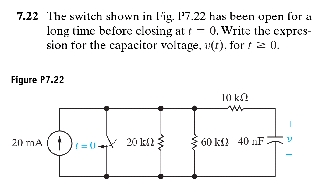
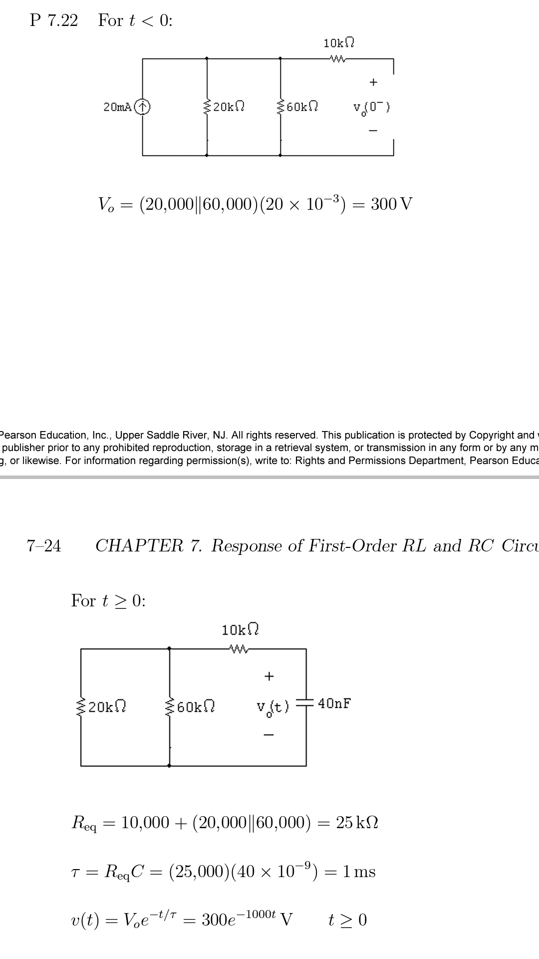
Seen below, they incorporated shorted resistor that doesn't affect the discharge rate in the time constant of capacitor. Why?


Original Question:

question

Answer:

Answer

\$\endgroup\$
19
  • 2
    \$\begingroup\$ I think your understanding is correct. You need to explain what makes you think you are wrong. \$\endgroup\$
    – Transistor
    Commented May 22, 2016 at 9:16
  • \$\begingroup\$ When capacitor goes to natural response when the gate shuts, T (tao) =RC Where R is R (eq). Here is the confusion. Since there's no current in the two resistors, R , seen by capacitor's view, shouldnt R (eq) be just 10K? The book is making R (eq) as (20k||6k)+10k \$\endgroup\$
    – Sysnaptic
    Commented May 22, 2016 at 9:23
  • \$\begingroup\$ Time to add a photo of the text, I think. \$\endgroup\$
    – Transistor
    Commented May 22, 2016 at 9:31
  • \$\begingroup\$ Sorry about the confusion. Text uploaded \$\endgroup\$
    – Sysnaptic
    Commented May 22, 2016 at 9:52
  • \$\begingroup\$ So what are you asking? Or do you want us to do your homework for you? \$\endgroup\$
    – EM Fields
    Commented May 22, 2016 at 9:58

1 Answer 1

4
\$\begingroup\$

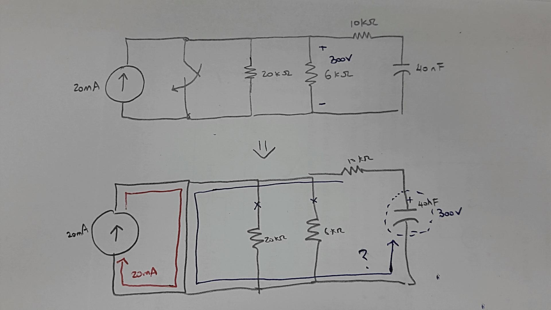
Responding to the handwritten portion of your question:

  1. Assuming the supply is a 20mA DC current source, then the 10k resistor and the capacitor can be ignored.
  2. The 20k and 6k resistors are in parallel, yielding an equivalent resistance of 4.6k ohms.
  3. with the switch open,20mA through 4.6k will drop 92 volts, not 300 volts.
  4. Since the closed switch will have some finite contact resistance, when it's closed there will be a small voltage dropped across the contacts, and that voltage will appear across the 4.6k, causing charge to flow through the resistance.

Assuming the voltage dropped across the closed switch is 10 millivolts, then the current through the 20k\$\Omega\$ resistor will be:

$$ I =\frac{E}{R}= \frac{0.01V}{20k\Omega} =500nA $$

and, through the 6k\$\Omega\$ resistor,

$$ I =\frac{E}{R}= \frac{0.01V}{6k\Omega} \approx 1.7\mu A $$

Responding to the 7-24 portion of your post, the circuit on the left, below, is with C1 charging up to 300 volts through R3, as shown by the green trace, and the circuit on the right is with C1 discharging through R1, R2, and R3, as shown by the red trace. T0 is that instant in time when the switch goes from made to open. I've added the LTspice circuit list following the graphic just in case you want to play around with the circuit.
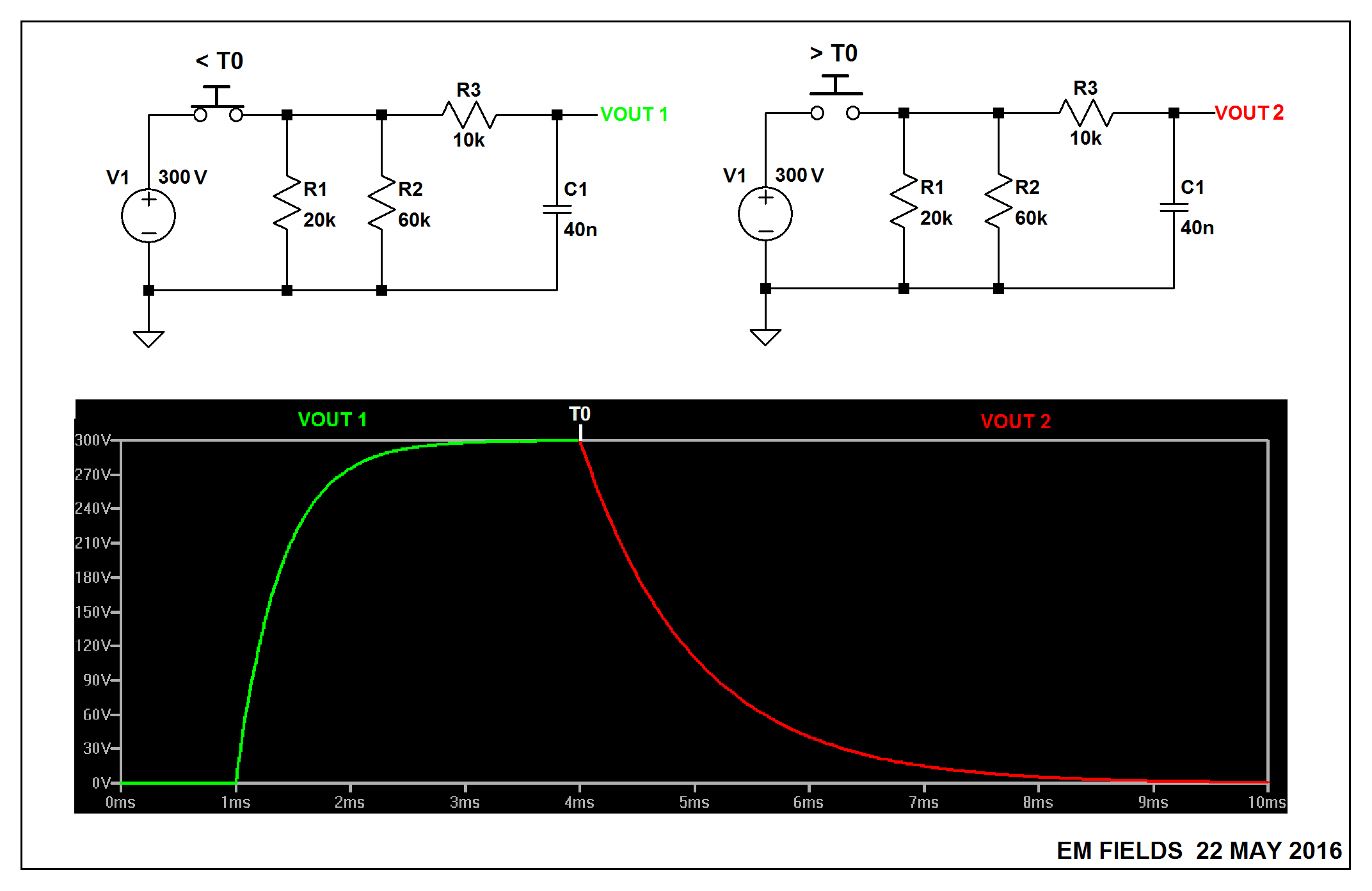
enter image description here

Version 4
SHEET 1 880 680
WIRE -32 32 -144 32
WIRE 112 32 48 32
WIRE 224 32 112 32
WIRE 288 32 224 32
WIRE 432 32 368 32
WIRE 480 32 432 32
WIRE 112 96 112 32
WIRE 224 96 224 32
WIRE -144 112 -144 32
WIRE -16 112 -16 80
WIRE 432 112 432 32
WIRE -144 240 -144 192
WIRE -16 240 -16 192
WIRE -16 240 -144 240
WIRE 32 240 32 80
WIRE 32 240 -16 240
WIRE 112 240 112 176
WIRE 112 240 32 240
WIRE 224 240 224 176
WIRE 224 240 112 240
WIRE 432 240 432 176
WIRE 432 240 224 240
WIRE -144 320 -144 240
FLAG -144 320 0
FLAG 480 32 VOUT1
SYMBOL res 96 80 R0
SYMATTR InstName R1
SYMATTR Value 20k
SYMBOL res 208 80 R0
SYMATTR InstName R2
SYMATTR Value 60k
SYMBOL res 384 16 R90
WINDOW 0 0 56 VBottom 2
WINDOW 3 32 56 VTop 2
SYMATTR InstName R3
SYMATTR Value 10k
SYMBOL voltage -144 96 R0
WINDOW 0 -50 10 Left 2
WINDOW 3 -60 104 Left 2
WINDOW 123 0 0 Left 2
WINDOW 39 0 0 Left 2
SYMATTR InstName V1
SYMATTR Value 300
SYMBOL cap 416 112 R0
SYMATTR InstName C1
SYMATTR Value 40n
SYMBOL sw 64 32 M270
SYMATTR InstName S1
SYMBOL voltage -16 96 R0
WINDOW 0 -46 7 Left 2
WINDOW 3 24 96 Invisible 2
WINDOW 123 0 0 Left 2
WINDOW 39 0 0 Left 2
SYMATTR InstName V2
SYMATTR Value PULSE(0 1 1m 100n 100n 3m)
TEXT -126 288 Left 2 !.tran 10m
TEXT -128 264 Left 2 !.model SW SW(Ron=.01 Roff=1G Vt=0.5 Vh=0)
\$\endgroup\$
7
  • \$\begingroup\$ Wow this is great thank you so much for the awesome answer! \$\endgroup\$
    – Sysnaptic
    Commented May 22, 2016 at 12:43
  • \$\begingroup\$ @dong6241: You're welcome. :) \$\endgroup\$
    – EM Fields
    Commented May 22, 2016 at 13:11
  • 1
    \$\begingroup\$ @EMFields, what cad you use? \$\endgroup\$
    – Antonio
    Commented Jul 27, 2016 at 15:10
  • \$\begingroup\$ @Antonio: LTspice, available here for free. \$\endgroup\$
    – EM Fields
    Commented Jul 27, 2016 at 18:05
  • \$\begingroup\$ Thanks @EMFields ! I know LTspice but I never opened *.asc files. \$\endgroup\$
    – Antonio
    Commented Jul 27, 2016 at 21:22

Your Answer

By clicking “Post Your Answer”, you agree to our terms of service and acknowledge you have read our privacy policy.

Not the answer you're looking for? Browse other questions tagged or ask your own question.