1
\$\begingroup\$

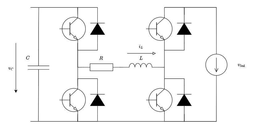
Let's say I have following circuit

enter image description here

where the transistors are controlled via a software in the microcontroller.

I have been looking for a control algorithm how to achieve a state when both of the upper transistors are open (turned on) and this state has been achieved without transient in the LC circuit. It is worthwhile to say that both of the inductor current (\$i_L\$) and capacitor voltage (\$v_C\$) are measurable.

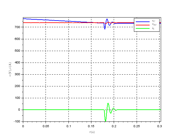
I have tried a naive approach when I open both of the transistors when the capacitor voltage (\$v_C\$) is equal to the source voltage (\$v_{bat}\$). Unfortunately this approach doesn't lead to success - the transient in the LC circuit occurs as can be seen in the attached graph.

enter image description here

Edit:

  1. As far as the decrease of the capacitor voltage \$v_C\$ in the time interval \$<0, 0.18>\,\mathrm{s}\$. The voltage decrease is caused by transistor switching in the below given circuit enter image description here
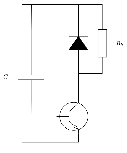
which is connected in parallel to the capacitor. The transistor is controlled also by the software in the microcontroller. The idea behind gradually reducing of the capacitor voltage was to balance the capacitor and battery voltage before opening (turning on) the upper transistors (I supposed that it should be sufficient for elimination of the transient).

  1. As far as the nominal values of the passive elements

\$R = 19\,\mathrm{m\Omega}\$, \$L = 1\,\mathrm{mH}\$, \$C = 3.36\,\mathrm{mF}\$, \$R_b = 1.32\,\mathrm{\Omega}\$.

\$\endgroup\$
6
  • \$\begingroup\$ Q1. What is causing the capacitor voltage to fall toward the battery voltage - is there some load connected that is not shown in the schematic? Q2. What are the typical values for the passive components shown: L, R, C? Q3. What is the time constant of the link network (L/R) compared to the time-constant of the output network (C and any load that is discharging it)? \$\endgroup\$ Commented Jun 25 at 9:36
  • \$\begingroup\$ @FabioBarone thank you for your reaction. I have just attempted to answer your questions via editing my question. \$\endgroup\$
    – Steve
    Commented Jun 25 at 14:05
  • 1
    \$\begingroup\$ When you say "opening the upper transistors", do you mean turning on the upper transistors? \$\endgroup\$ Commented Jun 25 at 16:04
  • \$\begingroup\$ @FabioBarone Yes. I am sorry for unclear nomenclature. \$\endgroup\$
    – Steve
    Commented Jun 25 at 19:04
  • \$\begingroup\$ I think a PID controller with constants set to compensate RLC transient can achieve zero overshoot. A PID algorithm running on MCU can be found on web. \$\endgroup\$ Commented Jun 26 at 5:57

1 Answer 1

1
\$\begingroup\$

I have been looking for a control algorithm how to achieve a state when both of the upper transistors are open and this state has been achieved without transient in the LC circuit.

I don't believe there is a solution that solves this completely. You are storing energy in the inductor from the battery and then releasing that energy into the capacitor some short time later. You are bound to get a damped resonant oscillation. It's therefore a numbers-game where you attempt to get that ripple voltage down to an acceptable level.

Storing/transferring less energy but more frequently will reduce the capacitor ripple (as will increasing the size of the capacitor). Standard practice in this type of converter.

\$\endgroup\$
2
  • \$\begingroup\$ Thank you for your answer. I have been thinking about the state space approach and design state feedback controller stabilizing the system. What do you think about this idea? \$\endgroup\$
    – Steve
    Commented Jun 25 at 14:33
  • \$\begingroup\$ I don't naturally design these types of circuit using the state-space approach hence, you can regard that approach as alien to me = I can't advise. \$\endgroup\$
    – Andy aka
    Commented Jun 25 at 15:26

Your Answer

By clicking “Post Your Answer”, you agree to our terms of service and acknowledge you have read our privacy policy.

Not the answer you're looking for? Browse other questions tagged or ask your own question.