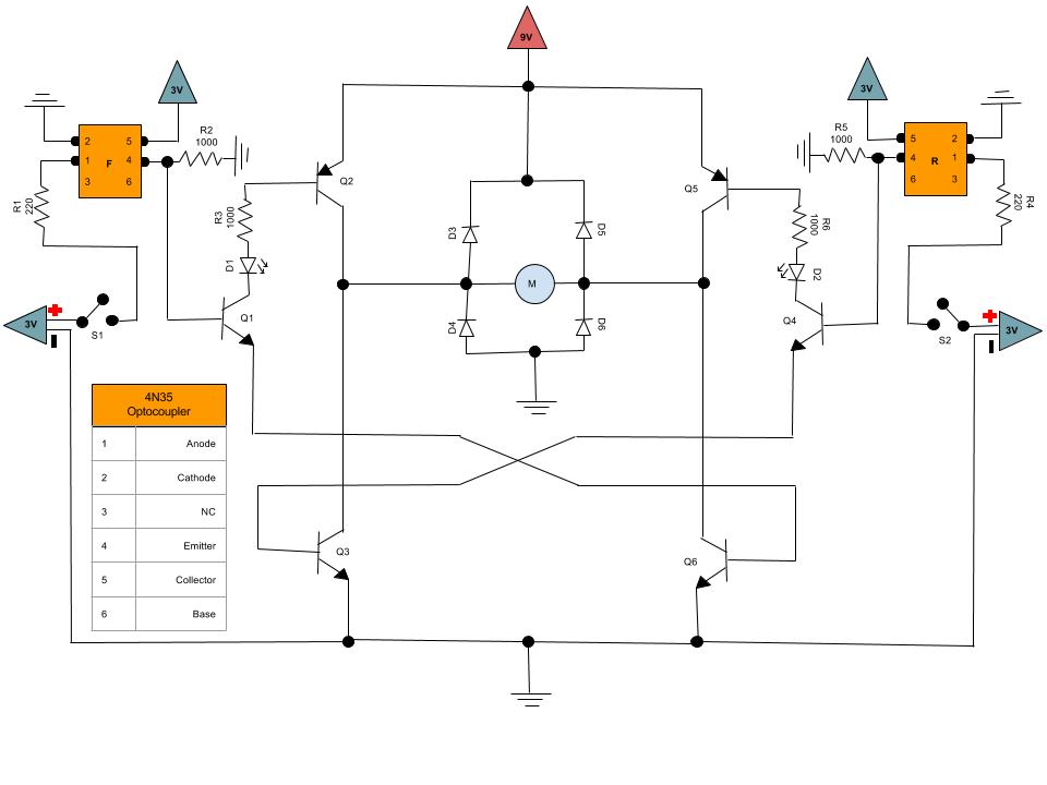
I am using the following h-bridge setup using optocouplers, a DC motor and bipolar junction transistors (2N3904 for the NPN and 2N3906 for the PNP)
Everything works as expected, but my question has to do with the voltage readings.
S1 is on
9v Battery = 9.5V (it is brand new, measured directly across anode and cathode)
9v Battery when motor is running = 8.8V (measured on the positive and ground rails)
Voltage across motor (disconnected) = 8.8V (measured with motor directly connected to the battery, disconnected from the h-bridge)
Voltage across motor (connected and running) = 6.4V (measured at the connection points between D4-D3 and D5-D6)
Vce Q2 = 0.8V (measured directly on the pins)
Vce Q6 = 0.3V (measured directly on the pins)
Vce Q1 = 0.02V (measured directly on the pins)
Voltage across R3 = 4.45V (measured directly on the leads)
From what I understand, with this setup (using BJTs) there is going to be a voltage drop. But there seems to be a discrepancy from the transistor readings and the motor voltage. Do these readings represent an inefficiency in the circuit or could there be an underlying issue?
If it has to do with the inefficiency of the circuit, are there better options? (I can't use an integrated circuit due to design restrictions)

